Nissan Almera Tino V10 (2001 year). Manual - part 156


  Index      Manuals     Nissan Almera Tino V10 (2001 year) - Service and Repair Manual


Search            copyright infringement  


Content      ..     154      155      156      157     ..


Nissan Almera Tino V10 (2001 year). Manual - part 156


JEM200G

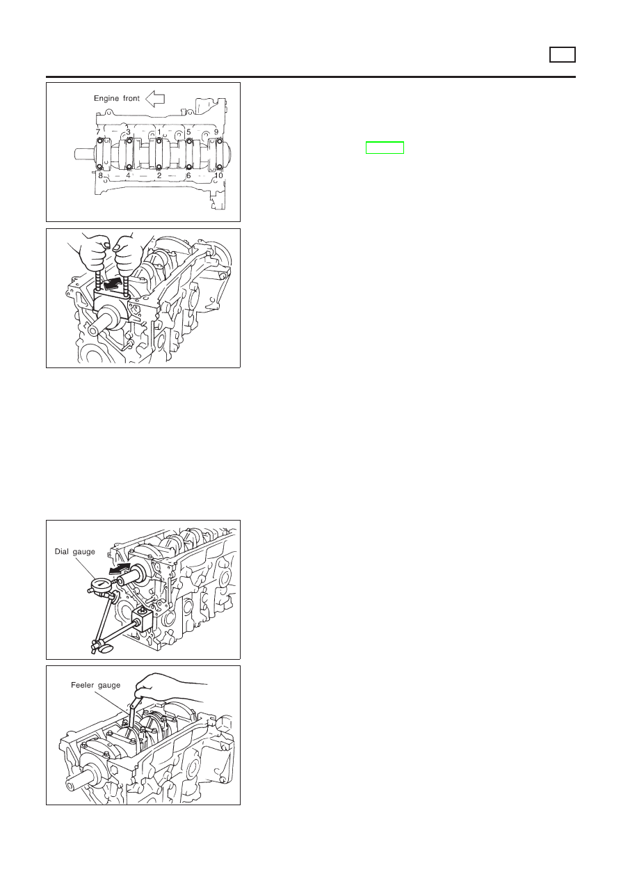
13. Remove main bearing cap bolts.

+

With a TORX socket (size: E-14, Commercial Service Tool),
loosen main bearing cap bolts in several stages in the reverse
order of that shown in the figure and remove them.

+

Before loosening main bearing cap bolts, measure crankshaft
end play. Refer to EM-225, “CRANKSHAFT END PLAY”.

JEM201G

14. Remove main bearing caps.

+

Using main bearing cap bolts, remove by rocking bearing cap
back and forth.

15. Remove crankshaft.
16. Remove main bearings and thrust bearings from cylinder block

and main bearing caps.

+

Check the correct installation locations of removed parts.
Store them so they do not get mixed up.

17. Remove oil jet.
18. Remove oil jet check valve.

JEM202G

Inspection

NLEM0073

CRANKSHAFT END PLAY

NLEM0073S13

+

Measure the moving distance of the crankshaft with the dial
gauge when the crankshaft is moved fully forward or back-
ward.

Standard: 0.10 - 0.25 mm (0.0039 - 0.0098 in)
Limit: 0.30 mm (0.0118 in)

+

If the value exceeds the limit, replace thrust bearings with new
ones and measure again. If the measurement exceeds the limit
again, replace crankshaft with a new one.

JEM203G

CONNECTING ROD SIDE CLEARANCE

NLEM0073S14

+

Measure the side clearance between connecting rod and crank
arm with feeler gauge.

Standard: 0.200 - 0.350 mm (0.0079 - 0.0138 in)
Limit: 0.4 mm (0.0157 in)

+

If the value exceeds the limit, replace connecting rod and mea-
sure again. If the measurement exceeds the limit again,
replace the crankshaft.

CYLINDER BLOCK

YD

Disassembly (Cont’d)

EM-225

AEM023

PISTON AND PISTON PIN CLEARANCE

NLEM0073S01

1.

Measure inner diameter of piston pin hole “dp”.

Standard diameter “dp”:

27.997 - 28.005 mm (1.1022 - 1.1026 in)

AEM024

2.

Measure outer diameter of piston pin “Dp”.

Standard diameter “Dp”:

27.994 - 28.000 mm (1.1021 - 1.1024 in)

3.

Calculate interference fit of piston pin to piston.

Dp − dp = 0.002 - 0.006 mm (0.0001 - 0.0002 in)

If it exceeds the above value, replace piston assembly with pin.

PISTON RING SIDE CLEARANCE

NLEM0073S02

Side clearance:

Top ring

0.050 - 0.090 mm (0.0020 - 0.0035 in)

2nd ring

0.050 - 0.090 mm (0.0020 - 0.0035 in)

Oil ring

0.030 - 0.070 mm (0.0012 - 0.0028 in)

Max. limit of side clearance:

Top ring 0.2 mm (0.008 in)
2nd ring 0.1 mm (0.004 in)

JEM205G

+

To measure top ring side clearance, align the outer circumfer-
ences of the ring and piston while pressing ring upward against
the upper surface of the ring groove. Under this condition,
measure the clearance between ring and bottom surface of the
ring groove.

+

If out of specification, replace piston ring. If clearance exceeds
maximum limit with new ring, replace piston.

SEM599A

PISTON RING END GAP

NLEM0073S03

End gap:

Top ring 0.20 - 0.35 mm (0.0079 - 0.0138 in)
2nd ring 0.39 - 0.54 mm (0.0154 - 0.0213 in)
Oil ring 0.25 - 0.50 mm (0.0098 - 0.0197 in)

Max. limit of ring gap:

Top ring 1.0 mm (0.039 in)
2nd ring 1.0 mm (0.039 in)
Oil ring 1.0 mm (0.039 in)

CYLINDER BLOCK

YD

Inspection (Cont’d)

EM-226

If out of specification, replace piston ring. If gap still exceeds the
limit even with a new ring, do the following. Rebore cylinder and
use oversized piston and piston rings.
Refer to SDS (EM-248).

+

When replacing the piston, check the cylinder block surface for
scratches or seizure. If scratches or seizure is found, hone or
replace the cylinder block.

SEM038F

SEM003F

CONNECTING ROD BEND AND TORSION

NLEM0073S04

Bend:

Limit 0.12 mm (0.0047 in)
per 100 mm (3.94 in) length

Torsion:

Limit 0.12 mm (0.0047 in)
per 100 mm (3.94 in) length

If it exceeds the limit, replace connecting rod assembly.

SEM501G

CYLINDER BLOCK DISTORTION AND WEAR

NLEM0073S05

+

Clean upper surface of cylinder block.
Use a reliable straightedge and feeler gauge to check the flat-
ness of cylinder block surface.
Check along six positions shown in the figure.

Distortion limit: 0.04 mm (0.0016 in)

+

If out of specification, resurface it. The limit for cylinder block
resurfacing is determined by cylinder head resurfacing in
engine.
Resurfacing limit:
Amount of cylinder head resurfacing is “A”.
Amount of cylinder block resurfacing is “B”.

The maximum limit is as follows:

A + B = 0.07mm (0.0028 in)

Nominal cylinder block height from crankshaft center:

252.95 - 253.05 mm (9.9586 - 9.9626 in)

+

If necessary, replace cylinder block.

CYLINDER BLOCK

YD

Inspection (Cont’d)

EM-227

JEM206G

JEM207G

PISTON-TO-BORE CLEARANCE

NLEM0073S06

1.

Using a bore gauge, measure cylinder bore in X and Y direc-
tions at A, B and C for wear, out-of-round and taper.

Cylinder bore inner diameter:

Standard

86.000 - 86.030 mm (3.3858 - 3.3870 in)

Wear limit

0.20 mm (0.0079 in)

If it exceeds the limit, rebore all cylinders. Replace cylinder
block if necessary.

Out-of-round (X − Y):

Limit 0.015 mm (0.0006 in)

Taper (A − B − C):

Limit 0.010 mm (0.0004 in)

2.

Check for scratches and seizure. If seizure is found, hone it.

SEM258C

3.

Measure piston skirt diameter.

Piston diameter “A”:

Standard

85.920 - 85.950 mm (3.3827 - 3.3839 in)

Measuring point “a” (Distance from the top):

58.0 mm (2.28 in)

4.

Check that piston-to-bore clearance is within specification.

+

Calculate the clearance by using outer diameter at piston skirt
and inner diameter of cylinder (direction of X, point B):

Piston-to-bore clearance = Cylinder bore – Piston
diameter “A”
Standard [at room temperature 20°C (68°F)]:

0.070 - 0.090 mm (0.0028 - 0.0035 in)

+

If the value is out of the specified range, replace piston and
piston pin assembly.

JEM208G

+

If cylinder block or pistons are replaced with new ones, select
piston as follows:

When using a new cylinder block:

+

Identify the cylinder bore grade (No. 1, 2, or 3) on LH surface
at the rear of cylinder block and select a piston of the same
grade.

+

The part No. of piston is specified together with the piston pin
as an assembly.

CYLINDER BLOCK

YD

Inspection (Cont’d)

EM-228

SEM509G

When re-using a removed cylinder block:

+

Measure the inner diameter of the cylinder block bore.

+

Determine the bore grade by comparing the measurement with
the values under “Cylinder bore ID” of the table below. Choose
a piston of the same grade.

Selective fitting for piston:

Unit: mm (in)

Grade (punched)

1

2

3

Cylinder bore ID

86.000 - 86.010

(3.3858 - 3.3862)

86.010 - 86.020

(3.3862 - 3.3866)

86.020 - 86.030

(3.3866 - 3.3870)

Piston OD

85.920 - 85.930

(3.3827 - 3.3831)

85.930 - 85.940

(3.3831 - 3.3835)

85.940 - 85.950

(3.3835 - 3.3839)

5.

Determine piston oversize according to amount of cylinder
wear.

+

For oversize pistons, 0.25 and 0.5OS [0.25 mm (0.0098 in),
0.5 mm (0.0197 in) oversize] are available as service parts.
Refer to SDS, EM-248. 
When using an oversize piston,
hone cylinder so that the clearance between piston and
cylinder becomes the specified value. Be sure to use
appropriate oversize piston ring for the oversize piston.

6.

Cylinder bore size is determined by adding piston-to-bore
clearance to piston diameter “A”.

Rebored size calculation: D = A + B − C

where,
D: Bored diameter
A: Piston diameter as measured
B: Piston-to-bore clearance
C: Honing allowance 0.02 mm (0.0008 in)

7.

Cut cylinder bores.

+

When any cylinder needs boring, all other cylinders must
also be bored.

+

Do not cut too much out of cylinder bore at a time. Cut
only 0.05 mm (0.0020 in) or so in diameter at a time.

8.

Hone cylinders to obtain specified piston-to-bore clearance.

9.

Measure finished cylinder bore for out-of-round and taper.

+

Measurement should be done after cylinder bore cools
down.

SEM316A

CRANKSHAFT

NLEM0073S07

1.

Check crankshaft main and pin journals for score, wear or
cracks.

2.

With a micrometer, measure journals for taper and out-of-
round.

Out-of-round (X − Y):

Standard

0.003 mm (0.0001 in)

Limit

0.005 mm (0.0002 in)

Taper (A − B):

CYLINDER BLOCK

YD

Inspection (Cont’d)

EM-229

Standard

0.003 mm (0.0001 in)

Limit

0.005 mm (0.0002 in)

JEM212G

3.

Measure crankshaft runout at No. 3 (center) journal.

Runout (Total indicator reading):

Standard 0.05 mm (0.0020 in)
Limit 0.10 mm (0.0039 in)

JEM214G

MAIN BEARING HOUSING INNER DIAMETER

NLEM0073S15

+

Without installing main bearings, install main bearing caps,
and tighten bolts to the specified torque.

+

Measure the inner diameter of main bearing housing with a
bore gauge.

Standard:

66.654 - 66.681 mm (2.6242 - 2.6252 in) dia.

+

If the measurement is out of the specified range, replace cyl-
inder block and main bearing caps.

JEM213G

BEARING CLEARANCE

NLEM0073S08

+

Use either of the following two methods, however, method “A”
gives more reliable results and is preferable.

Method A (Using bore gauge & micrometer)

Main bearing

NLEM0073S0801

1.

Install main bearings to the cylinder block and bearing cap, and
tighten the bolts to the specified torque. Then, measure the
inner diameter of the main bearings.

Oil clearance = Bearing ID – Crankshaft journal OD
Standard: 0.039 - 0.066 mm (0.0015 - 0.0026 in)

2.

If the value is out of the specified range, select main bearings
to obtain the specified oil clearance, based on the measure-
ments of the main bearing housing inner diameter and crank-
shaft journal outer diameter.

CYLINDER BLOCK

YD

Inspection (Cont’d)

EM-230

JEM208G

When using a new cylinder block and crankshaft:
1)

Identify the bearing housing grade (No. 0, 1, or 2) on LH sur-
face at the rear of the cylinder block, and locate the applicable
grade on the “Grade” row in the table below.

2)

Identify the journal grade (No. 0, 1, or 2) on the front surface
of the crankshaft, and locate the applicable grade under the
“Grade” column on the table.

3)

The main bearing to be used (STD 0 to STD 4) can be located
in the cell where the row and column cross.

JEM215G

When re-using removed cylinder block and crankshaft:
1)

Measure the inner diameter of cylinder block main bearing
housing.

2)

Locate the applicable cell where the measurement falls, on
“Cylinder block main bearing housing ID” row on the table.

3)

Measure the outer diameter of the crankshaft journal.

4)

Locate the applicable cell where the measurement falls, under
“Crankshaft journal OD” column on the table.

5)

The main bearing to be used (STD 0 to STD 4) can be located
in the cell where the row and column cross.

Selective fitting for main bearing

Unit: mm (in)

Cylinder block main bearing housing ID

66.654 - 66.663

(2.6242 - 2.6245)

66.663 - 66.672

(2.6245 - 2.6249)

66.672 - 66.681

(2.6249 - 2.6252)

Crankshaft journal

OD

Grade

(punched)

0

1

2

62.967 - 62.975

(2.4790 - 2.4793)

0

+

Bearing grade No.

+

Bearing thickness

+

Oil clearance

+

Identification color

STD 0

1.816 - 1.820

(0.0715 - 0.0717)

0.039 - 0.066

(0.0015 - 0.0026)

Black

STD 1

1.820 - 1.824

(0.0717 - 0.0718)

0.039 - 0.066

(0.0015 - 0.0026)

Brown

STD 2

1.824 - 1.828

(0.0718 - 0.0720)

0.039 - 0.066

(0.0015 - 0.0026)

Green

62.959 - 62.967

(2.4787 - 2.6790)

1

+

Bearing grade No.

+

Bearing thickness

+

Oil clearance

+

Identification color

STD 1

1.820 - 1.824

(0.0717 - 0.0718)

0.039 - 0.066

(0.0015 - 0.0026)

Brown

STD 2

1.824 - 1.828

(0.0718 - 0.0720)

0.039 - 0.066

(0.0015 - 0.0026)

Green

STD 3

1.828 - 1.832

(0.0720 - 0.0721)

0.039 - 0.066

(0.0015 - 0.0026)

Yellow

62.951 - 62.959

(2.4784 - 2.4787)

2

+

Bearing grade No.

+

Bearing thickness

+

Oil clearance

+

Identification color

STD 2

1.824 - 1.828

(0.0718 - 0.0720)

0.039 - 0.066

(0.0015 - 0.0026)

Green

STD 3

1.828 - 1.832

(0.0720 - 0.0721)

0.039 - 0.066

(0.0015 - 0.0026)

Yellow

STD 4

1.832 - 1.836

(0.0721 - 0.0723)

0.039 - 0.066

(0.0015 - 0.0026)

Blue

3.

When the specified oil clearance is not obtained with standard
size main bearings, use undersized bearings.

+

When an undersized bearing is used, measure the inner diam-
eter of the bearing while the bearing is installed. Grind crank-
shaft journal so that the specified oil clearance is obtained.

CYLINDER BLOCK

YD

Inspection (Cont’d)

EM-231

JEM216G

Undersize bearing

Unit: mm (in)

Size

Thickness

US 0.25 (0.0098)

1.949 - 1.953 (0.0767 - 0.0769)

CAUTION:

When grinding the crankshaft journal to use an undersize
bearing, avoid damaging the fillet R.

AEM027

Connecting Rod Bearing (Big end)

NLEM0073S0802

1.

Install connecting rod bearing to connecting rod and cap.

2.

Install connecting rod cap to connecting rod.
Tighten bolts to the specified torque.

3.

Measure inner diameter “C” of connecting rod.

Inner diameter:

Standard 55.000 - 55.013 mm (2.1654 - 2.1659 in)

AEM034

4.

Measure outer diameter “Dp” of each crankshaft pin journal.

5.

Calculate connecting rod bearing clearance.
Connecting rod bearing clearance = C − Dp

Standard: 0.031 - 0.061 mm (0.0012 - 0.0024 in)

6.

If it exceeds the standard, replace bearing.

JEM215G

When using a new crankshaft and connecting rods:

+

Identify the pin diameter grade (No. 0, 1, or 2) on front surface
of crankshaft and select the connecting rod bearings of the
same grade.

+

There is no grading for the inner diameter of the big end of the
connecting rod.

When re-using the removed crankshaft and connecting rods:

+

Measure the inner diameter of the big end of the connecting
rod and make sure it is within the specified range.

+

Measure the outer diameter of the crankshaft pin.

+

Determine the crankshaft pin grade by comparing the mea-
surement with the values under the column “Crankshaft pin
OD” of the table below. Choose the bearings of the same
grade.

Selective fitting for connecting rod bearing

Unit: mm (in)

Connecting rod big end ID

55.000 - 55.013 (2.1654 - 2.1659)

Crankshaft pin OD

Grade (punched)

0 (no punching)

CYLINDER BLOCK

YD

Inspection (Cont’d)

EM-232

51.968 - 51.974

(2.0460 - 2.0462)

0

+

Bearing grade No.

+

Bearing thickness

+

Oil clearance

+

Identification color

STD 0

1.492 - 1.496

(0.0587 - 0.0589)

0.031 - 0.061

(0.0012 - 0.0024)

Black

51.961 - 51.968

(2.0457 - 2.0460)

1

+

Bearing grade No.

+

Bearing thickness

+

Oil clearance

+

Identification color

STD 1

1.496 - 1.500

(0.0589 - 0.0591)

0.031 - 0.061

(0.0012 - 0.0024)

Brown

51.954 - 51.961

(2.0454 - 2.0457)

2

+

Bearing grade No.

+

Bearing thickness

+

Oil clearance

+

Identification color

STD 2

1.500 - 1.504

(0.0591 - 0.0592)

0.031 - 0.061

(0.0012 - 0.0024)

Green

7.

If clearance cannot be adjusted within the standard of any
bearing, grind crankshaft journal and use undersized bearing.

+

When an undersized bearing is used, measure the inner diam-
eter of the bearing while the bearing is installed. Grind the pins
so that the specified oil clearance is obtained.

JEM216G

Undersize bearing

Unit: mm (in)

Size

Thickness

US 0.08 (0.0031)

1.536 - 1.540 (0.0605 - 0.0606)

US 0.12 (0.0047)

1.556 - 1.560 (0.0613 - 0.0614)

US 0.25 (0.0098)

1.621 - 1.625 (0.0638 - 0.0640)

CAUTION:

When grinding the crankshaft journal to use an undersize
bearing, avoid damaging the fillet R.

Standard dimension R:

1.5 - 1.7 mm (0.0591 - 0.0669 in)

CYLINDER BLOCK

YD

Inspection (Cont’d)

EM-233

EM142

Method B (Using plastigage)

CAUTION:

+

Do not turn crankshaft or connecting rod while plastigage
is being inserted.

+

When bearing clearance exceeds the specified limit,
ensure that the proper bearing has been installed. If incor-
rect bearing clearance exists, use a thicker or undersized
main bearing to ensure specified clearance.

SEM502G

MAIN BEARING CRUSH HEIGHT

NLEM0073S16

+

When the bearing cap is removed after being tightened to the
specified torque with main bearings installed, the tip end of
bearing must protrude.

Standard: There must be crush height.

+

If the standard is not met, replace main bearings.

JEM219G

MAIN BEARING CAP BOLT DEFORMATION

NLEM0073S17

+

Measure the outer diameter of threaded area, d1 and d2, at the
points specified in the figure.

+

When the necked point is identified at a point other than where
specified, measure at the point as d2.

+

Calculate the difference between d1 and d2.

Limit: 0.13 mm (0.0051 in)

SEM673E

CONNECTING ROD BUSHING CLEARANCE (SMALL
END)

NLEM0073S09

1.

Measure inner diameter “C” of bushing.

Inner diameter “C”:

Standard 28.026 - 28.038 mm (1.1034 - 1.1039 in)

2.

Measure outer diameter “Dp” of piston pin.

Outer diameter “Dp”:

Standard 27.994 - 28.000 mm (1.1021 - 1.1024 in)

3.

Calculate connecting rod bushing clearance.
Connecting rod bushing clearance = C − Dp

Standard: 0.026 - 0.044 mm (0.0010 - 0.0017 in)
Limit: 0.057 mm (0.0022 in)

If it exceeds the limit, replace connecting rod assembly and/or
piston set with pin.

CYLINDER BLOCK

YD

Inspection (Cont’d)

EM-234

JEM220G

CONNECTING ROD BOLT DEFORMATION

NLEM0073S18

+

Install nuts to connecting rod bolts. Check that the nut can be
screwed smoothly on bolt threads by hand to the last thread
on the bolt.

+

If the nut does not screw in smoothly, measure the outer diam-
eter of the bolt thread at the point specified in the figure.

+

If a necked point is identified, measure at that point.

Standard: 8.90 - 9.00 mm (0.3504 - 0.3543 in) dia.
Limit: 8.75 mm (0. 3445 in) dia.

+

If the measurement exceeds the limit, replace connecting rod
bolts and nuts.

AEM100

FLYWHEEL RUNOUT

NLEM0073S11

Runout (Total indicator reading):

Flywheel

Less than 0.15 mm (0.0059 in)

CAUTION:

+

The signal plate is built into the flywheel assembly. Be
careful not to damage the signal plate, especially the
teeth.

+

Check the signal plate for deformation or cracks.

+

Never place the flywheel assembly with the signal plate
facing down.

+

Keep any magnetized objects away from the signal plate.

+

Do not allow any magnetic materials to contact the signal
plate teeth.

JEM221G

OIL JET

NLEM0073S19

+

Check nozzle for deformation or damage.

+

Check oil passage for obstruction by blowing in air on nozzle
side.

+

If abnormality is found, clean or replace.

JEM222G

OIL JET RELIEF VALVE

NLEM0073S20

Using a clean resin rod, press down on the check valve inside relief
valve. Check for appropriate bounce/repulsion and smooth
operation.

CYLINDER BLOCK

YD

Inspection (Cont’d)

EM-235

Assembly

NLEM0074

PISTON

NLEM0074S01

1.

With using snap ring pliers, install snap rings to grooves at the
rear side of the piston.

+

Install securely to fully fit into the groove.

2.

Install piston to the connecting rod.

+

Heat the piston with an industrial drier to 60 to 70°C (140 to
158°F) so that the piston pin can be easily inserted by finger.
Then, insert the piston pin from the front of the piston into the
piston and into the connecting rod.

JEM227G

+

Assemble so that the front mark on the piston top surface and
cylinder No. stamped on connecting rod are positioned as
shown in the figure.

3.

Install snap ring on piston front.

+

Refer to step 1. above for notes for installation.

+

After installing, check that the connecting rod moves smoothly.

4.

Install piston rings using piston ring expander (Commercial
Service Tool).

+

Be extremely careful to avoid any damage to the piston.

JEM228G

+

Install top ring and second ring with the punched surface fac-
ing upward.

Identification mark:

Top ring AE
Second ring AE2

+

Install rings so that three closed gap position 120° apart one
another.

+

Closed gaps do not need to face in a specific directions, as
long as each are positioned 120° apart.

JEM223G

CRANKSHAFT

NLEM0074S02

1.

Blow air sufficiently into the coolant passage, oil passage in the
cylinder block, inside of crankshaft case, and inside of cylinder
bores to remove any foreign materials.

2.

Install oil jet relief valves.

3.

Install oil jets.

JEM224G

4.

Install main bearings and thrust bearings.

a.

Remove debris, dust, and oil from the locations on the cylin-
der block and main bearing caps where bearings are installed.

b.

Install thrust bearing on each side of cylinder block No. 3
housing.

+

Install thrust bearings with oil groove facing in the direction of
the crankshaft arm (outside).

CYLINDER BLOCK

YD

Assembly

EM-236

JEM213G

c.

Be sure to install main bearings in the correct direction.

+

Make sure those with oil holes or oil grooves are mounted on
the cylinder block side, and those without oil holes or oil
grooves are on the main cap side.

+

Before installing, apply engine oil on the front (inner) surfaces
of bearings. Do not apply oil to the back surfaces, but thor-
oughly clean them.

+

Align stopper notches on bearings and install.

+

Check the oil holes on cylinder block and those on bearings
are aligned.

JEM225G

5.

Install crankshaft to cylinder block.

+

Make sure crankshaft rotates smoothly by hand.

6.

Install main bearing caps.

+

Identify main bearing caps by the punched mark. Install
correctly, matching the journal No. on the bearing cap and the
journal, with the front mark facing forward.

+

Main bearing caps are commonly processed with the cylinder
block. Therefore, caps and cylinder block should be replaced
as a set.

JEM200G

JEM226G

7.

Check the main bearing cap bolts for deformation.
Refer to EM-234, “MAIN BEARING CAP BOLT DEFORMA-
TION”.

8.

Tighten the main bearing cap bolts according to the following
procedure:

a.

Apply engine oil to the threaded part and seat surface of each
bolt.

b.

Tighten to 25 to 30 N·m (2.5 to 3.1 kg-m, 18 to 22 ft-lb) in the
numerical order shown in the figure.

c.

Put alignment marks (with paint) on each bolt and the main
bearing cap, all in the same direction. (when using a protrac-
tor)

d.

Then, tighten 90° to 95° [target: 90°].

+

Always use either an angle wrench (SST) or protractor
during angular tightening. Avoid tightening based on
visual checks alone.

+

After tightening bolts to specified torque, make sure that crank-
shaft rotates smoothly.

+

Check crankshaft end play. Refer to EM-225, “CRANKSHAFT
END PLAY”.

9.

Check the outer diameter of connecting rod bolts. Refer to
EM-235, “CONNECTING ROD BOLT DEFORMATION”.

10. Install piston to connecting rod.

CYLINDER BLOCK

YD

Assembly (Cont’d)

EM-237

JEM229G

11. Install connecting rod bearing to connecting rod and connect-

ing rod cap.

+

Before installing, apply engine oil on the front (inner) surface
of bearing. Do not apply oil to the back surface, but thoroughly
clean it.

+

Align stopper notches on connecting rod and protrusions on
bearing and install.

JEM230G

12. Install piston and connecting rod assembly to crankshaft.

+

Set crankshaft pin of the installation location at BDC.

+

Match the cylinder No. of connecting rod to the location of cyl-
inder.

+

Using piston ring compressor (Commercial Service Tool),
install so that the front mark on the piston top surface faces in
the direction of engine front.

JEM227G

13. Install connecting rod caps.

+

Match the cylinder No. punched on connecting rod and that on
cap.

+

Make sure that the front mark on connecting rod cap faces
towards the front of the engine.

JEM231G

JEM232G

14. Tighten connecting rod nuts according to the following proce-

dure:

a.

Apply engine oil on bolt threads and seat surface of nuts.

b.

Tighten to 29 to 30 N·m (2.9 to 3.1 kg-m, 21 to 22 ft-lb).

c.

Loosen completely to 0 N·m (0 kg-m, 0 in-lb).

d.

Tighten to 19 to 20 N·m (1.9 to 2.1 kg-m, 14 to 15 ft-lb).

e.

Tighten 120° to 125° [target: 120°]. (angular tightening)

+

Always use either an angle wrench (SST) or protractor
during angular tightening. Avoid tightening based on
visual checks alone.

+

After tightening nuts, check that crankshaft rotates smoothly.

+

Check connecting rod side clearance. Refer to EM-225, “CON-
NECTING ROD SIDE CLEARANCE”.

15. Force fit rear oil seal into rear oil seal retainer.

+

Using a drift [105 mm (4.13 in) dia.], force fit so that the dimen-
sion is as specified in the figure.

+

Avoid inclined fitting. Force fit perpendicularly.

CYLINDER BLOCK

YD

Assembly (Cont’d)

EM-238

JEM233G

16. Install rear oil seal retainer.

+

Apply a continuous bead of specified liquid gasket (Refer to
EM-158, “Liquid Gasket Application Procedure”.) on locations
shown in the figure.

JEM234G

17. Install pilot bushing.

+

Force fit with the drift [approx. 19 mm (0.75 in) dia.].

SEM513G

18. Install fuel injection pump bracket.

+

Install insulator according to the shape of the block, and secure
by placing the bracket against the insulator. (Not installed on
some models)

+

Align the bracket with the dowel pins on the block to install.

+

The two bolts used for dowel pins have a longer shanks than
the other two.

+

Check the protruding distance of the dowel pin for fuel injec-
tion pump.

Standard: 13.0 - 15.0 mm (0.512 - 0.591 in)

19. Install parts to the engine in the reverse order of disassembly.

+

Tighten bolts securing brackets of auxiliary components (A/C
compressor, alternator) to the specified torque.

: 57 - 65 N·m (5.8 - 6.7 kg-m, 42 - 48 ft-lb)

20. Remove engine from engine stand in the reverse order of

assembly.

21. Install flywheel.

+

Holding ring gear with ring stopper (SST), tighten securing
bolts with TORX-socket (size: Q8 E20, Commercial Service
Tool).

+

Tighten bolts uniformly in a crisscross manner.

SEM500G

REPLACEMENT OF PILOT BUSHING

NLEM0074S03

1.

Remove pilot bushing using tool or suitable tool.

CYLINDER BLOCK

YD

Assembly (Cont’d)

EM-239

SEM275G

2.

Install pilot bushing as shown.

CYLINDER BLOCK

YD

Assembly (Cont’d)

EM-240


Content      ..     154      155      156      157     ..