Nissan Almera Tino V10 (2001 year). Manual - part 153
JEM126G
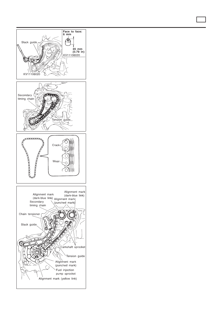
6.
Remove timing chain slack guide.
+
Using a hexagon-head wrench (face to face: 6 mm, SST),
remove bolt to remove timing chain slack guide.
JEM127G
7.
Remove timing chain tension guide.
8.
Remove secondary timing chain.
+
Timing chain alone can be removed without removing sprock-
ets.
SEM885F
INSPECTION
NLEM0093S02
Check for cracks and excessive wear at roller links. Replace
chain if necessary.
JEM128G
INSTALLATION
NLEM0093S03
1.
Install secondary timing chain.
+
When installing, match the alignment marks on sprockets with
color coded alignment marks (colored links) on the chain.
2.
Install timing chain tension guide.
+
The upper bolt has a longer shank than the lower bolt.
TIMING CHAIN
YD
Secondary Timing Chain (Cont’d)
EM-177