Index Manuals Nissan Almera Tino V10 (2001 year) - Service and Repair Manual
Search copyright infringement
Content .. 59 60 61 62 ..
Nissan Almera Tino V10 (2001 year). Manual - part 61
YEC678
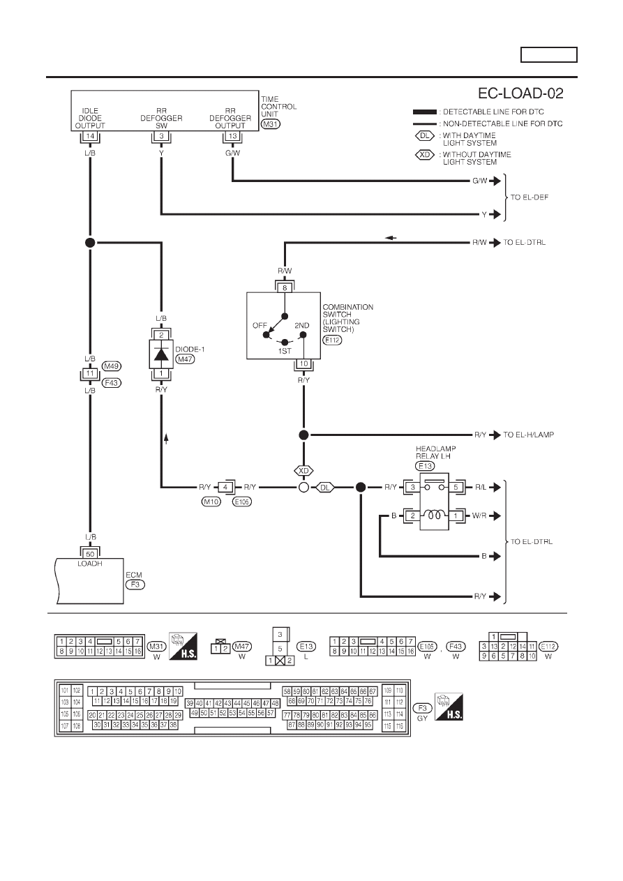
ELECTRICAL LOAD SIGNAL
QG18DE
Wiring Diagram (Cont’d)
EC-537