Nissan Almera Tino V10 (2001 year). Manual - part 46
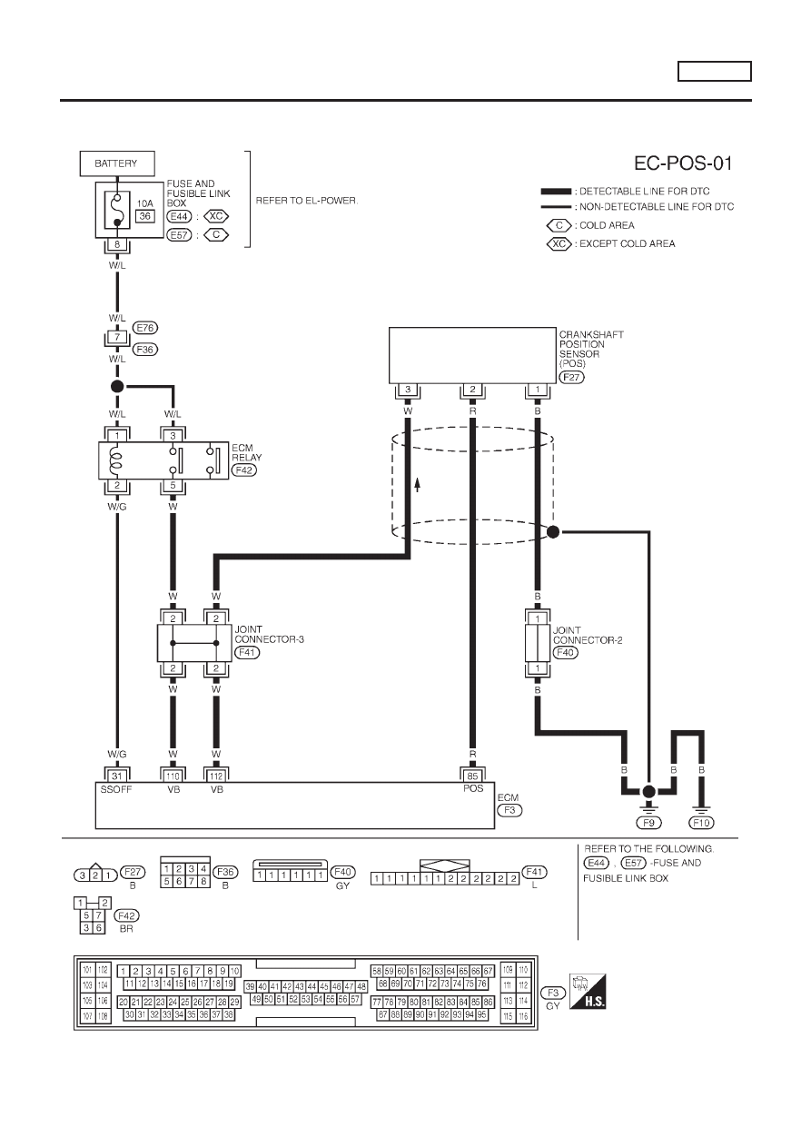
Wiring Diagram
NLEC0555
MODELS WITH ECM IN ENGINE COMPARTMENT
NLEC0555S01
YEC662
DTC P0335 CRANKSHAFT POSITION SENSOR (POS)
QG18DE
Wiring Diagram
EC-297
|
|
|
Wiring Diagram NLEC0555 MODELS WITH ECM IN ENGINE COMPARTMENT NLEC0555S01 YEC662 DTC P0335 CRANKSHAFT POSITION SENSOR (POS) QG18DE Wiring Diagram EC-297 |