Nissan Almera Tino V10 (2001 year). Manual - part 43
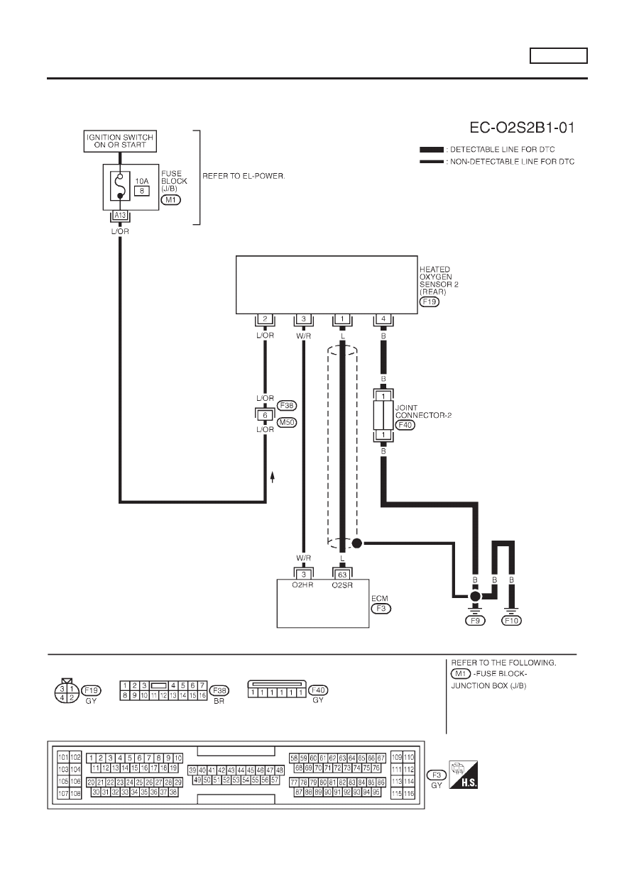
Wiring Diagram
NLEC0168
MODELS WITH ECM IN ENGINE COMPARTMENT
NLEC0168S03
YEC693
DTC P0139 HEATED OXYGEN SENSOR 2 (REAR)
(RESPONSE MONITORING)
QG18DE
Wiring Diagram
EC-249
|
|
|
Wiring Diagram NLEC0168 MODELS WITH ECM IN ENGINE COMPARTMENT NLEC0168S03 YEC693 DTC P0139 HEATED OXYGEN SENSOR 2 (REAR) (RESPONSE MONITORING) QG18DE Wiring Diagram EC-249 |