Nissan Almera Tino V10. Manual - part 854


  Index      Nissan     Nissan Almera Tino V10 - Service Manual (2003 year)


Search            


Content   ..  852  853  854  855   ..


Nissan Almera Tino V10. Manual - part 854


EM-72

[QG]

ENGINE ASSEMBLY

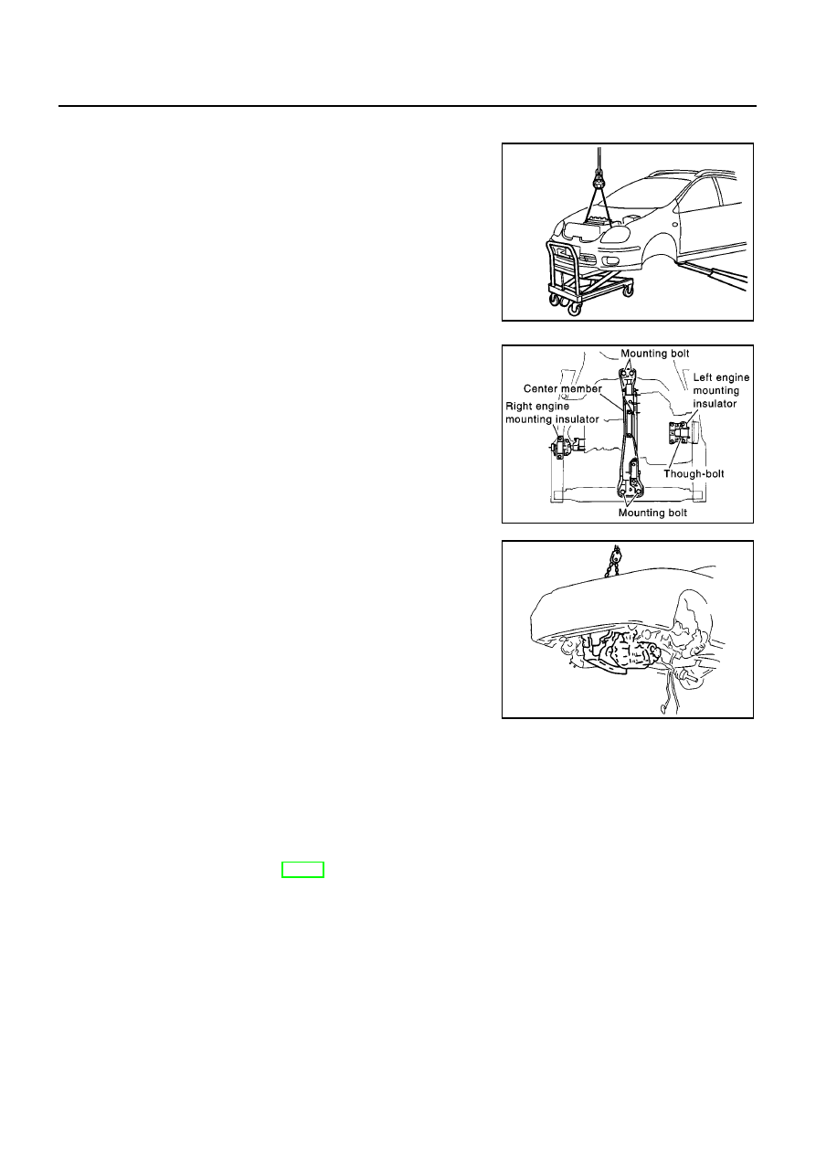
19. Install lifting chain hooks into engine slinger and suspend engine with hoist.

20. Lift with hoist and secure the engine in position.

Use a manual lift table caddy (commercial service tool) or
equivalently rigid tool such as a jack or trestle. Securely sup-
port bottom of engine and transaxle, and simultaneously
adjust hoist tension.

CAUTION:

Put a piece of wood or something similar as the sup-
porting surface, secure a completely stable condition.

21. Remove RH engine mounting insulator.

22. Pull LH engine mounting through-bolt out.

23. Remove mounting bolts at front and rear of center member.

24. Lower manual lift table caddy (or raise lift), and remove engine

transaxle assembly from vehicle.

CAUTION:

When carrying out this work, be sure to check all parts
for interference with vehicle body.

Be sure to check that all the applicable connections have
been properly disconnected.

Be careful to prevent vehicle from dropping off the lift. Be
aware that changes in center of gravity may cause bal-
ance incidents.

Disassembly

The following shows engine and transaxle disassembly on level ground.

CAUTION:

During disassembly, always support bottom with a wooden block. Suspend engine slinger with a
hoist. Be sure to check safety of work at any time.

25. Remove center member.

26. Remove engine mounting insulators and bracket.

27. Remove stater motor. Refer to SC-13, “Starting System”.

28. Separate engine and transaxle.

INSTALLATION

Install in the reverse order of removal.

Do not allow oil to get on mounting insulator. Be careful not to damage mounting insulator.

When installation directions are specified, install parts according to the direction marks on them referring
to components illustration.

Make sure that each mounting insulator is seated properly, and tighten mounting bolts and nuts.

INSPECTION AFTER INSTALLATION

Before starting engine, check the levels of coolant, lubrications and working oils. If less than required
quantity, fill to the specified level.

MBIA0041E

PBIC0583E

KBIA0227J

ENGINE ASSEMBLY

EM-73

[QG]

C

D

E

F

G

H

I

J

K

L

M

A

EM

Use procedure below to check for fuel leakage.
a. Turn ignition switch ON (with engine stopped). With fuel pressure applied to fuel piping, check for fuel
leakage at connection points.
b. Start engine. With engine speed increased, check again for fuel leakage at connection points.

Run engine to check for unusual noise and vibration.

Warm up engine thoroughly to make sure there is no leakage of coolant, lubricants, working oil, fuel and
exhaust gas.

Bleed air from passages in pipes and tubes of applicable lines, such as in cooling system.

After cooling down engine, again check amounts of coolant, lubricants, oil, and fluid. Refill to specified
level, if necessary.

EM-74

[QG]

CYLINDER BLOCK

CYLINDER BLOCK

PFP:11010

Disassembly and Assembly

EBS00QES

MBIA0042E

CYLINDER BLOCK

EM-75

[QG]

C

D

E

F

G

H

I

J

K

L

M

A

EM

CAUTION:

Apply new engine oil to parts marked in illustration before installation.

DISASSEMBLY

1.

Remove engine and transaxle assembly from vehicle, and separate transaxle from engine. Refer to

EM-

70, "Removal and Installation"

.

2.

Mount engine on an engine stand with the following procedure.

a.

Remove exhaust manifold and catalytic converter. Refer to

EM-21, "Removal and Installation"

.

b.

Remove engine front mounting bracket, alternator and air compressor bracket.

c.

Install engine sub-attachment to left side of cylinder block.

d.

Lift engine, and mount it onto the engine stand.

1.

Rear oil seal

2.

Rear oil seal retainer

3.

Crankshaft position sensor (POS)

4.

O-ring

5.

Knock sensor

6.

Oil level gauge guide

7.

Cylinder block

8.

Thrust bearing

9.

Main bearing

10. Crankshaft

11. Key

12. Top ring

13. 2nd ring

14. Oil ring

15. Main bearing

16. Piston

17. Snap ring

18. Piston pin

19. Connecting rod

20. Connecting rod bearing

21. Connecting rod cap

22. Connecting rod nut

23. Main bearing cap bolt

24. Baffle plate

25. Main bearing cap

26. Signal plate

27. Rear plate

28. Coolant drain plug

29. Flywheel (M/T models)

30. Drive plate (A/T models)

PBIC0585E

PBIC1017E


Content   ..  852  853  854  855   ..