Nissan Almera Tino V10. Manual - part 665


  Index      Nissan     Nissan Almera Tino V10 - Service Manual (2003 year)


Search            


Content   ..  663  664  665  666   ..


Nissan Almera Tino V10. Manual - part 665


EC-1486

[YD (WITHOUT EURO-OBD)]

DTC P2146, P2149 FUEL INJECTOR POWER SUPPLY

Diagnostic Procedure

EBS0150S

1.

CHECK FUEL INJECOR POWER CIRCUIT FOR OPEN AND SHORT

1.

Turn ignition switch OFF.

2.

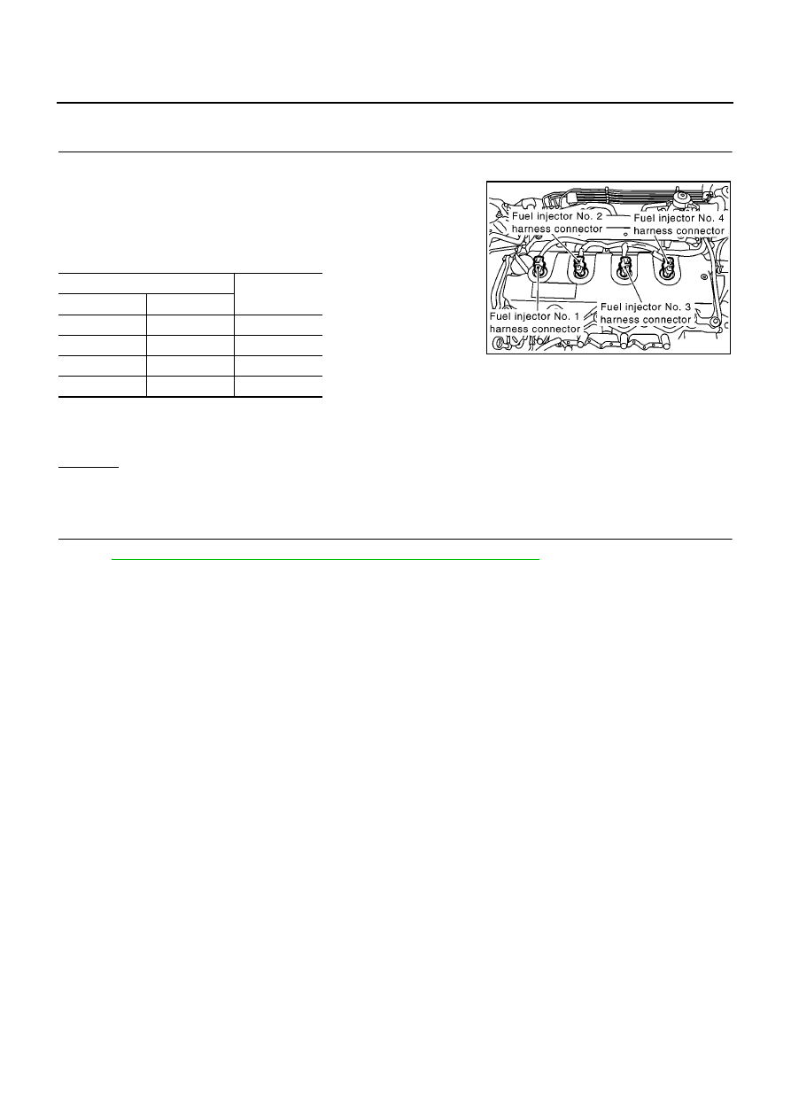
Disconnect fuel injector harness connector.

3.

Disconnect ECM harness connector.

4.

Check harness continuity between the following terminals corre-
sponding to the malfunctioning cylinder.
Refer to Wiring Diagram.

5.

Also check harness for short to ground and short to power.

OK or NG

OK

>> GO TO 2.

NG

>> Repair open circuit or short to ground or short to power in harness or connectors.

2.

CHECK INTERMITTENT INCIDENT

Refer to

EC-1309, "TROUBLE DIAGNOSIS FOR INTERMITTENT INCIDENT"

.

>> INSPECTION END

Terminal

Cylinder

ECM

Fuel injector

4

3

No.1

5

3

No.2

5

3

No.3

4

3

No.4

Continuity should exist.

MBIB0635E

DTC P2147, P2148 FUEL INJECTOR CIRCUIT

EC-1487

[YD (WITHOUT EURO-OBD)]

C

D

E

F

G

H

I

J

K

L

M

A

EC

DTC P2147, P2148 FUEL INJECTOR CIRCUIT

PFP:16600

Component Description

EBS0150T

The fuel injector is a small, precise solenoid valve. When the ECM
supplies a ground to the fuel injector circuit, the coil in the fuel injec-
tor is energized. The energized coil pulls the needle valve back and
allows fuel to flow through the fuel injector into the intake cylinder.
The amount of fuel injected depends upon the injection pulse dura-
tion. Pulse duration is the length of time the fuel injector remains
open. The ECM controls the injection pulse duration based on
engine fuel needs.

CONSULT-II Reference Value in Data Monitor Mode

EBS0150U

Specification data are reference values.

ECM Terminals and Reference Value

EBS0150V

Specification data are reference values and are measured between each terminal and ground.
Pulse signal is measured by CONSULT-II.

CAUTION:

Do not use ECM ground terminals when measuring input/output voltage. Doing so may result in dam-
age to the ECM's transistor. Use a ground other than ECM terminals, such as the ground.

PBIB0465E

MONITOR ITEM

CONDITION

SPECIFICATION

MAIN INJ WID

Engine: After warming up

Shift lever: Neutral position

Idle speed

No-load

0.68 - 0.78 msec

Blower fan switch: ON
Rear window defogger switch: ON

0.78 - 0.88 msec

TERMI-

NAL

NO.

WIRE

COLOR

ITEM

CONDITION

DATA

(DC Voltage and Pulse Signal)

4

5

O/B

B

Fuel injector power supply
(For cylinder No. 1 and 4)
Fuel injector power supply
(For cylinder No. 2 and 3)

[Engine is running]

Warm-up condition

Idle speed

5 - 10V

[Engine is running]

Warm-up condition

Engine speed is 2,000 rpm

5 - 10V

MBIB0883E

MBIB0884E

EC-1488

[YD (WITHOUT EURO-OBD)]

DTC P2147, P2148 FUEL INJECTOR CIRCUIT

: Average voltage for pulse signal (Actual pulse signal can be confirmed by oscilloscope.)

On Board Diagnosis Logic

EBS0150W

21
22
23
24

L
PU/W
L
PU/W

Fuel injector No. 2
Fuel injector No. 2
Fuel injector No. 3
Fuel injector No. 3

[Engine is running]

Warm-up condition

Idle speed

0 - 9V

[Engine is running]

Warm-up condition

Engine speed is 2,000 rpm

0 - 9V

40
41
42
43

B/P
PU/W
B/P
PU/W

Fuel injector No. 4
Fuel injector No. 4
Fuel injector No. 1
Fuel injector No. 1

[Engine is running]

Warm-up condition

Idle speed

0 - 9V

[Engine is running]

Warm-up condition

Engine speed is 2,000 rpm

0 - 9V

TERMI-

NAL

NO.

WIRE

COLOR

ITEM

CONDITION

DATA

(DC Voltage and Pulse Signal)

MBIB0881E

MBIB0882E

MBIB0881E

MBIB0882E

DTC No.

Trouble diagnosis name

DTC detecting condition

Possible cause

P2147

Fuel injector circuit low input

ECM detects the fuel injector circuit is shorted to
ground.

Harness or connectors
(The fuel injector circuit is shorted.)

P2148

Fuel injector circuit high input

ECM detects the fuel injector circuit is shorted to
power.

DTC P2147, P2148 FUEL INJECTOR CIRCUIT

EC-1489

[YD (WITHOUT EURO-OBD)]

C

D

E

F

G

H

I

J

K

L

M

A

EC

DTC Confirmation Procedure

EBS0150X

NOTE:
If DTC Confirmation Procedure has been previously conducted, always turn ignition switch OFF and wait at
least 10 seconds before conducting the next test.

WITH CONSULT-II

1.

Turn ignition switch ON.

2.

Select “DATA MONITOR” mode with CONSULT-II.

3.

Start engine and let it idle for at least 5 seconds.

4.

If DTC is detected, go to

EC-1491, "Diagnostic Procedure"

.

SEF817Y


Content   ..  663  664  665  666   ..