Nissan Almera Tino V10. Manual - part 644


  Index      Nissan     Nissan Almera Tino V10 - Service Manual (2003 year)


Search            


Content   ..  642  643  644  645   ..


Nissan Almera Tino V10. Manual - part 644


EC-1402

[YD (WITHOUT EURO-OBD)]

DTC P0336 CKP SENSOR

On Board Diagnosis Logic

EBS014WU

DTC Confirmation Procedure

EBS014WV

NOTE:
If DTC Confirmation Procedure has been previously conducted, always turn ignition switch OFF and wait at
least 10 seconds before conducting the next test.
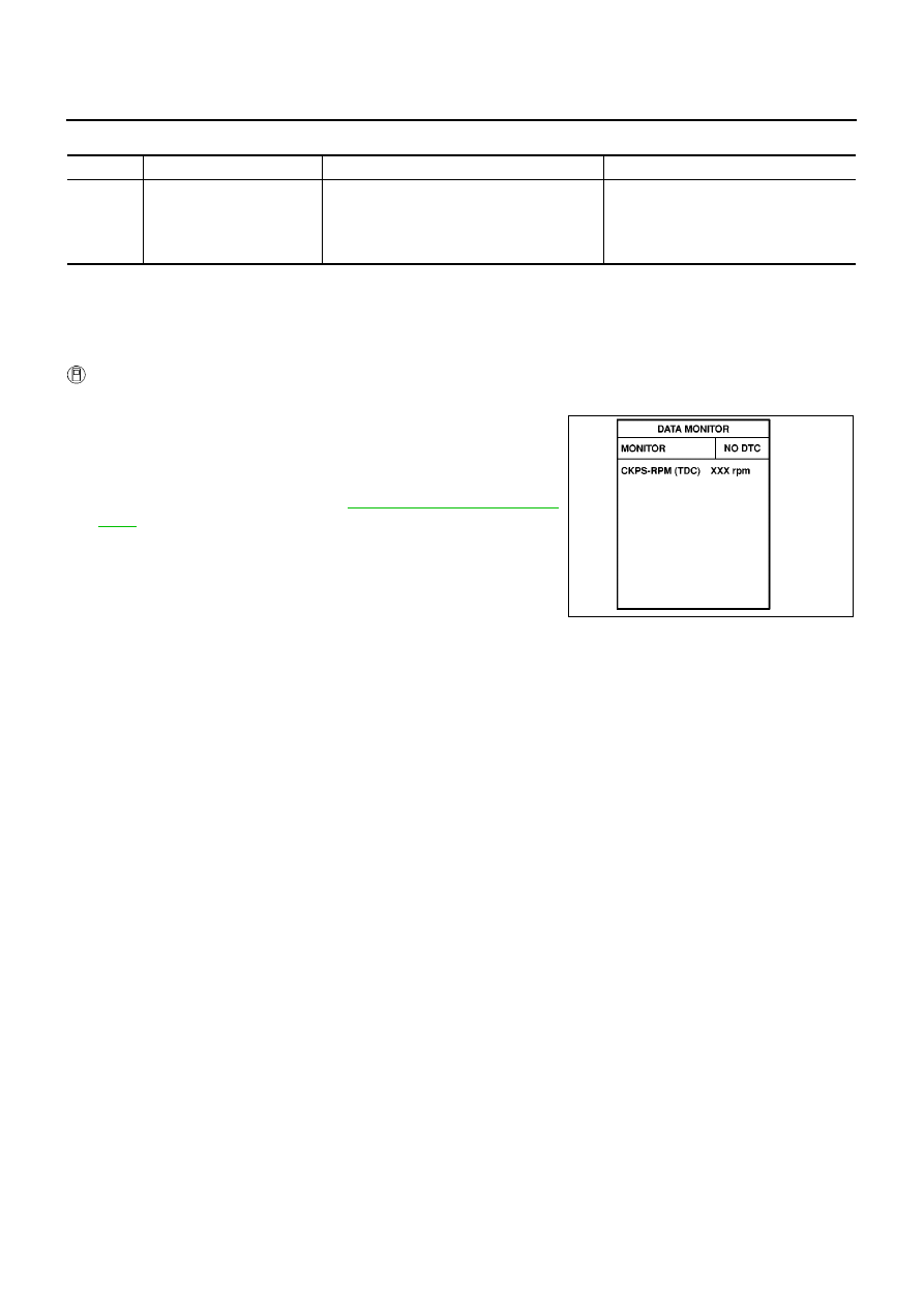
WITH CONSULT-II

1.

Turn ignition switch ON.

2.

Select “DATA MONITOR” mode with CONSULT-II.

3.

Start engine and let it idle for at least 5 seconds.
If engine could not start, keep ignition switch at START position
for 5 seconds.

4.

If 1st trip DTC is detected, go to

EC-1404, "Diagnostic Proce-

dure"

.

DTC No.

Trouble diagnosis name

DTC detecting condition

Possible cause

P0336

Crankshaft position sensor
circuit range/performance

Crankshaft position sensor signal is not in the
normal pattern when engine is running.

Harness or connectors
(The sensor circuit is open or shorted.)

Crankshaft position sensor

Signal plate

SEF817Y

DTC P0336 CKP SENSOR

EC-1403

[YD (WITHOUT EURO-OBD)]

C

D

E

F

G

H

I

J

K

L

M

A

EC

Wiring Diagram

EBS014WW

YEC504A

EC-1404

[YD (WITHOUT EURO-OBD)]

DTC P0336 CKP SENSOR

Diagnostic Procedure

EBS014WX

1.

CHECK GROUND CONNECTIONS

1.

Turn ignition switch OFF.

2.

Loosen and retighten body ground screw. Refer to

EC-1317,

"Ground Inspection"

.

OK or NG

OK

>> GO TO 2.

NG

>> Repair or replace ground connection.

2.

CHECK CKP SENSOR POWER SUPPLY CIRCUIT

1.

Disconnect crankshaft position sensor harness connector.

2.

Turn ignition switch ON.

3.

Check voltage between CKP sensor terminal 3 and ground with
CONSULT-II or tester.

4.

Also check harness for short to ground and short to power.

OK or NG

OK

>> GO TO 3.

NG

>> Repair open circuit or short to ground or short to power

in harness or connectors.

3.

CHECK CKP SENSOR GROUND CIRCUIT FOR OPEN AND SHORT

1.

Turn ignition switch OFF.

2.

Disconnect ECM harness connector.

3.

Check harness continuity between ECM terminal 65 and CKP sensor terminal 2.
Refer to Wiring Diagram.

4.

Also check harness for and short to ground and short to power.

OK or NG

OK

>> GO TO 4.

NG

>> Repair open circuit or short to ground or short to power in harness or connectors.

MBIB0915E

MBIB0863E

Voltage: Approximately 5.3V

SEF646P

Continuity should exist.

DTC P0336 CKP SENSOR

EC-1405

[YD (WITHOUT EURO-OBD)]

C

D

E

F

G

H

I

J

K

L

M

A

EC

4.

CHECK CKP SENSOR INPUT SIGNAL CIRCUIT FOR OPEN AND SHORT

1.

Check harness continuity between ECM terminal 46 and CKP sensor terminal 1.
Refer to Wiring Diagram.

2.

Also check harness for short to ground and short to power.

OK or NG

OK

>> GO TO 5.

NG

>> Repair open circuit or short to ground or short to power in harness or connectors.

5.

CHECK CRANKSHAFT POSITION SENSOR

Refer to

EC-1405, "Component Inspection"

.

OK or NG

OK

>> GO TO 6.

NG

>> Replace crankshaft position sensor.

6.

CHECK GEAR TOOTH

Visually check for chipping signal plate gear tooth.

OK or NG

OK

>> GO TO 7.

NG

>> Replace the signal plate.

7.

CHECK INTERMITTENT INCIDENT

Refer to

EC-1309, "TROUBLE DIAGNOSIS FOR INTERMITTENT INCIDENT"

.

>> INSPECTION END

Component Inspection

EBS014WY

CRANKSHAFT POSITION SENSOR

1.

Loosen the fixing bolt of the sensor.

2.

Disconnect crankshaft position sensor harness connector.

3.

Remove the sensor.

4.

Visually check the sensor for chipping.

Continuity should exist.

MBIB0864E


Content   ..  642  643  644  645   ..