Nissan Almera Tino V10. Manual - part 631


  Index      Nissan     Nissan Almera Tino V10 - Service Manual (2003 year)


Search            


Content   ..  629  630  631  632   ..


Nissan Almera Tino V10. Manual - part 631


EC-1350

[YD (WITHOUT EURO-OBD)]

DTC P0182, P0183 FUEL PUMP TEMPERATURE SENSOR

Diagnostic Procedure

EBS014UY

1.

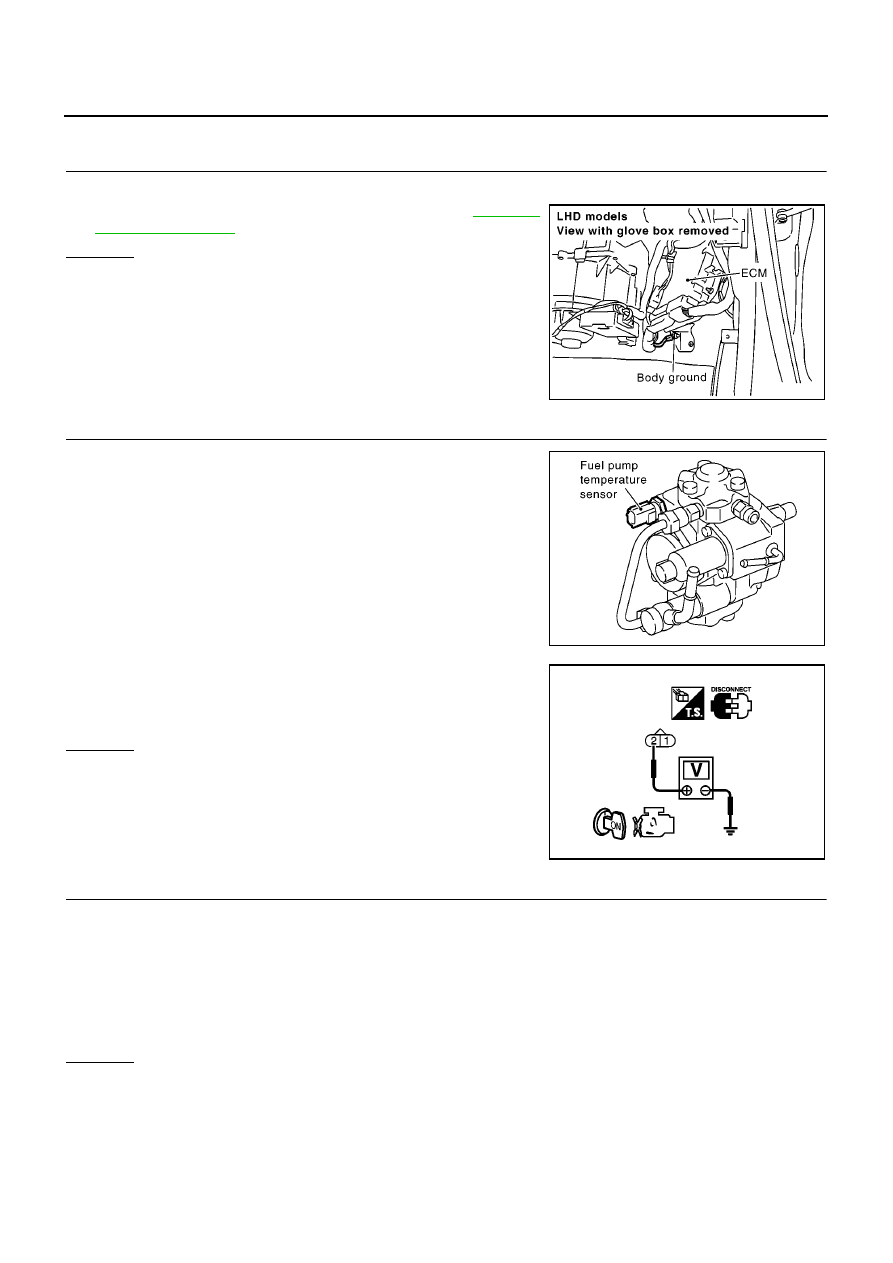
CHECK GROUND CONNECTIONS

1.

Turn ignition switch OFF.

2.

Loosen and retighten body ground screw. Refer to

EC-1317,

"Ground Inspection"

.

OK or NG

OK

>> GO TO 2.

NG

>> Repair or replace ground connection.

2.

CHECK FUEL PUMP TEMPERATURE SENSOR POWER SUPPLY CIRCUIT

1.

Disconnect fuel pump temperature sensor harness connector.

2.

Turn ignition switch ON.

3.

Check voltage between fuel pump temperature sensor terminal
2 and ground with CONSULT-II or tester.

OK or NG

OK

>> GO TO 3.

NG

>> Repair harness or connectors.

3.

CHECK FUEL PUMP TEMPERATURE SENSOR GROUND CIRCUIT FOR OPEN AND SHORT

1.

Turn ignition switch OFF.

2.

Disconnect ECM harness connector.

3.

Check harness continuity between fuel pump temperature sensor terminal 1 and ECM terminal 69.
Refer to Wiring Diagram.

4.

Also check harness for short to ground and short to power.

OK or NG

OK

>> GO TO 4.

NG

>> Repair open circuit or short to ground or short to power in harness or connectors.

MBIB0915E

PBIB1942E

Voltage: Approximately 5.3V

MBIB0185E

Continuity should exist.

DTC P0182, P0183 FUEL PUMP TEMPERATURE SENSOR

EC-1351

[YD (WITHOUT EURO-OBD)]

C

D

E

F

G

H

I

J

K

L

M

A

EC

4.

CHECK INTERMITTENT INCIDENT

Refer to

EC-1309, "TROUBLE DIAGNOSIS FOR INTERMITTENT INCIDENT"

.

OK or NG

OK

>> GO TO 5.

NG

>> Repair or replace.

5.

REPLACE FUEL PUMP

1.

Replace fuel pump.

2.

Perform Fuel Pump Learning Value Clearing. Refer to

EC-1270, "Fuel Pump Learning Value Clearing"

.

>> INSPECTION END

Removal and Installation

EBS014UZ

FUEL PUMP

Refer to

EM-150, "FUEL PUMP"

.

EC-1352

[YD (WITHOUT EURO-OBD)]

DTC P0192, P0193 FRP SENSOR

DTC P0192, P0193 FRP SENSOR

PFP:16638

Description

EBS014V0

The fuel rail pressure (FRP) sensor is placed to the fuel rail. It measures the fuel pressure in the fuel rail. The
sensor sends voltage signal to the ECM. As the pressure increases, the voltage rises.
The ECM controls the fuel pressure in the fuel rail by the inlet throttling device. The ECM uses the signal from
fuel rail pressure sensor as a feedback signal.

CONSULT-II Reference Value in Data Monitor Mode

EBS014V1

Specification data are reference values.

ECM Terminals and Reference Value

EBS014V2

Specification data are reference values and are measured between each terminal and ground.

CAUTION:

Do not use ECM ground terminals when measuring input/output voltage. Doing so may result in dam-
age to the ECM's transistor. Use a ground other than ECM terminals, such as the ground.

On Board Diagnosis Logic

EBS014V3

The MI will not light up for these self-diagnoses.

MONITOR

CONDITION

SPECIFICATOIN

ACT CR PRESS

Engine: After warming up

Air conditioner switch: OFF

Shift lever: Neutral position

No-load

Idle

20 - 30 MPa

2,000 rpm

45 - 55 MPa

TERMI-

NAL

NO.

WIRE

COLOR

ITEM

CONDITION

DATA

(DC Voltage)

48
49

R
R

Fuel rail pressure sensor

[Engine is running]

Warm-up condition

Idle speed

1.7 - 2.0V

[Engine is running]

Warm-up condition

Engine speed is 2,000 rpm

2.0 - 2.3V

63

W

Fuel rail pressure sensor
power supply

[Ignition switch ON]

Approximately 5.3V

67

B

Sensor ground
(Sensors shield circuit)

[Ignition switch ON]

Approximately 0.3V

68

B

Fuel rail pressure sensor
ground

[Ignition switch ON]

Approximately 0.3V

DTC No.

Trouble diagnosis name

DTC detecting condition

Possible cause

P0192

Fuel rail pressure sensor
circuit low input

An excessively low voltage from the sensor is
sent to ECM.

Harness or connectors
(The sensor circuit is open or shorted.)

Fuel rail pressure sensor

P0193

Fuel rail pressure sensor
circuit high input

An excessively high voltage from the sensor is
sent to ECM.

DTC P0192, P0193 FRP SENSOR

EC-1353

[YD (WITHOUT EURO-OBD)]

C

D

E

F

G

H

I

J

K

L

M

A

EC

DTC Confirmation Procedure

EBS014V4

NOTE:
If DTC Confirmation Procedure has been previously conducted, always turn ignition switch OFF and wait at
least 10 seconds before conducting the next test.

WITH CONSULT-II

1.

Turn ignition switch ON.

2.

Select “DATA MONITOR” mode with CONSULT-II.

3.

Wait at least 5 seconds.

4.

If DTC is detected, go to

EC-1355, "Diagnostic Procedure"

.

SEF817Y


Content   ..  629  630  631  632   ..