Nissan Almera Tino V10. Manual - part 414


  Index      Nissan     Nissan Almera Tino V10 - Service Manual (2003 year)


Search            


Content   ..  412  413  414  415   ..


Nissan Almera Tino V10. Manual - part 414


EC-482

[QG (WITH EURO-OBD)]

DTC P1217 ENGINE OVER TEMPERATURE

7.

CHECK COOLING FAN MOTORS

Refer to

EC-483, "Component Inspection"

.

OK or NG

OK

>> GO TO 8.

NG

>> Replace cooling fan motors.

8.

CHECK SMART ENTRANCE CONTROL UNIT

Refer to “SMART ENTRANCE CONTROL SYSTEM”, EL-341.

OK or NG

OK

>> GO TO 9.

NG

>> Replace smart entrance control unit.

9.

CHECK INTERMITTENT INCIDENT

Perform

EC-138, "TROUBLE DIAGNOSIS FOR INTERMITTENT INCIDENT"

.

>> INSPECTION END

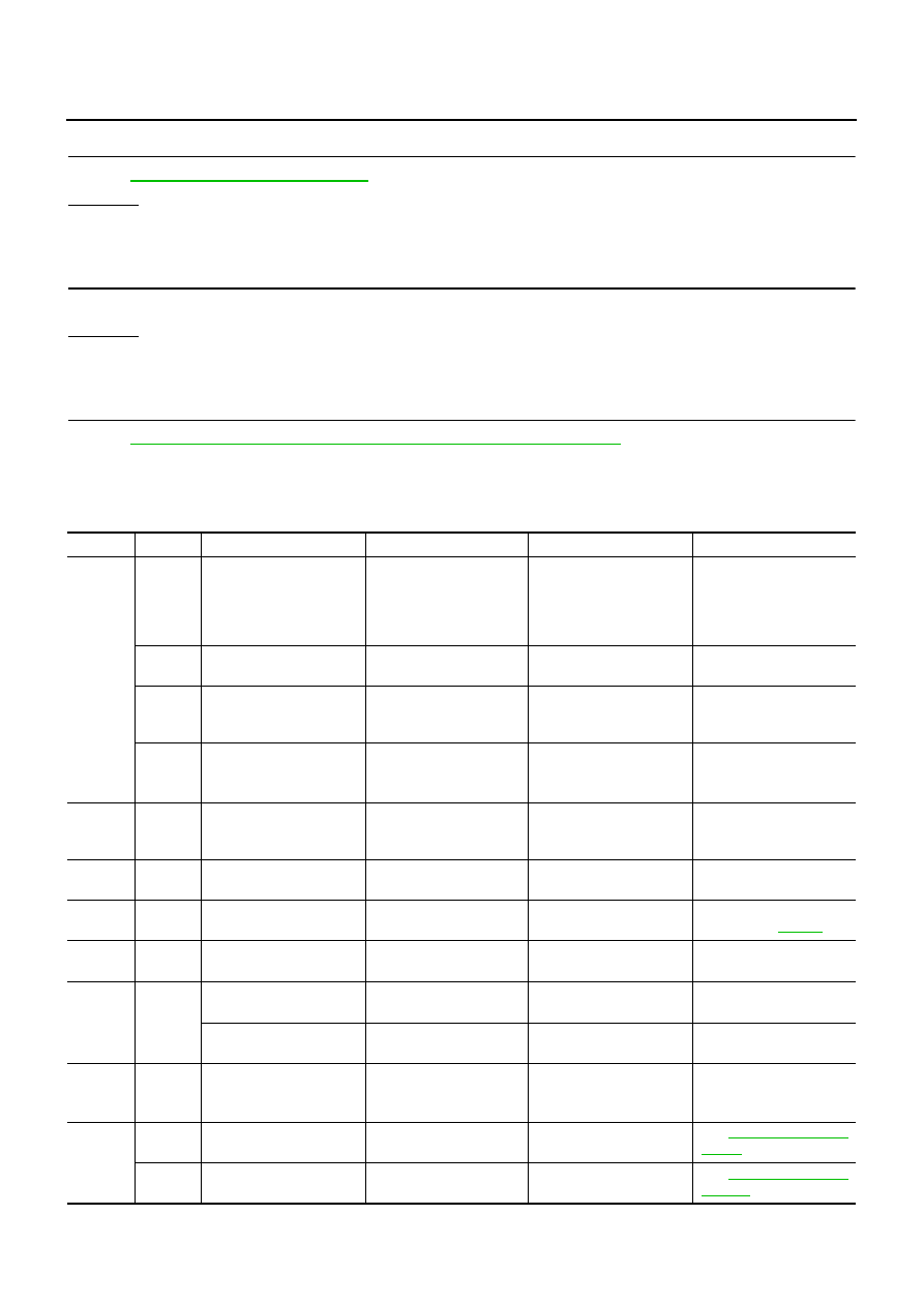
Main 12 Causes of Overheating

EBS00QRX

*1: Turn the ignition switch ON.

Engine

Step

Inspection item

Equipment

Standard

Reference page

OFF

1

Blocked radiator

Blocked condenser

Blocked radiator grille

Blocked bumper

Visual

No blocking

2

Coolant mixture

Coolant tester

50 - 50% coolant mixture

See “Engine Coolant Mix-
ture Ratio”, MA-15.

3

Coolant level

Visual

Coolant up to MAX level
in reservoir tank and radi-
ator filler neck

See “Changing Engine
Coolant”, LC-18.

4

Radiator cap

Pressure tester

59 - 98 kPa
(0.59 - 0.98 bar, 0.6 - 1.0

kg/cm

2

, 9 - 14 psi) (Limit)

See “CHENGING RADIA-
TOR CAP”, LC-13.

ON*

2

5

Coolant leaks

Visual

No leaks

See “CHENGING COOL-
ING SYSTEM FOR
LEAKS”, LC-13.

ON*

2

6

Thermostat

Touch the upper and
lower radiator hoses

Both hoses should be hot

See “Thermostat”, LC-15,
and “Radiator”, LC-16.

ON*

1

7

Cooling fan

CONSULT-II

Operating

See trouble diagnosis for
DTC P1217 (

EC-473

).

OFF

8

Combustion gas leak

Color checker chemical
tester 4 Gas analyzer

Negative

ON*

3

9

Coolant temperature
gauge

Visual

Gauge less than 3/4
when driving

Coolant overflow to
reservoir tank

Visual

No overflow during driving
and idling

See “Changing Engine
Coolant”, LC-18.

OFF*

4

10

Coolant return from
reservoir tank to radia-
tor

Visual

Should be initial level in
reservoir tank

See “Changing Engine
Coolant”, LC-18.

OFF

11

Cylinder head

Straight gauge feeler
gauge

0.1 mm (0.004 in) Maxi-
mum distortion (warping)

See

EM-60, "CYLINDER

HEAD"

.

12

Cylinder block and pis-
tons

Visual

No scuffing on cylinder
walls or piston

See

EM-74, "CYLINDER

BLOCK"

.

DTC P1217 ENGINE OVER TEMPERATURE

EC-483

[QG (WITH EURO-OBD)]

C

D

E

F

G

H

I

J

K

L

M

A

EC

*2: Engine running at 3,000 rpm for 10 minutes.
*3: Drive at 90 km/h (55 MPH) for 30 minutes and then let idle for 10 minutes.
*4: After 60 minutes of cool down time.
For more information, refer to “Overheating Cause Analysis”, LC-20.

Component Inspection

EBS00QRY

COOLING FAN RELAY-1

1.

Apply 12V direct current between relay terminals 1 and 2.

2.

Check continuity between relay terminals 3 and 5, 6 and 7.

3.

If NG, replace cooling fan relay.

COOLING FAN MOTORS-1 AND -2

1.

Disconnect cooling fan motor harness connectors.

2.

Supply cooling fan motor terminals with battery voltage and
check operation.

Cooling fan motor should operate.

3.

If NG, replace cooling fan motor.

Condition

Continuity

12V direct current supply
between terminals 1 and 2

Yes

OFF

No

PBIB0077E

Terminals

(+)

(

)

Cooling fan motor

1

2

MBIB0109E

EC-484

[QG (WITH EURO-OBD)]

DTC P1223, P1224 TP SENSOR

DTC P1223, P1224 TP SENSOR

PFP:16119

Component Description

EBS00QRZ

Electric Throttle Control Actuator consists of throttle control motor,
throttle position sensor, etc. The throttle position sensor responds to
the throttle valve movement.
The throttle position sensor has the two sensors. These sensors are
a kind of potentiometers which transform the throttle valve position
into output voltage, and emit the voltage signal to the ECM. In addi-
tion, these sensors detect the opening and closing speed of the
throttle valve and feed the voltage signals to the ECM. The ECM
judges the current opening angle of the throttle valve from these sig-
nals and the ECM controls the throttle control motor to make the
throttle valve opening angle properly in response to driving condi-
tion.

CONSULT-II Reference Value in Data Monitor Mode

EBS00QS0

Specification data are reference values.

*: Throttle position sensor 2 signal is converted by ECM internally. Thus, it differs from ECM terminal voltage signal.

On Board Diagnosis Logic

EBS00QS1

These self-diagnoses have the one trip detection logic.

FAIL-SAFE MODE

When the malfunction is detected, the ECM enters fail-safe mode and the MI lights up.

DTC Confirmation Procedure

EBS00QS2

NOTE:
If “DTC Confirmation Procedure” has been previously conducted, always turn ignition switch “OFF” and wait at
least 10 seconds before conducting the next test.
TESTING CONDITION:
Before performing the following procedure, confirm that battery voltage is more than 10V at idle.

PBIB0145E

MONITOR ITEM

CONDITION

SPECIFICATION

THRTL SEN1

THRTL SEN2

*

Ignition switch: ON
(Engine stopped)

Accelerator pedal: Fully released

More than 0.36V

Shift lever:
D (A/T model)
1st (M/T model)

Accelerator pedal: Fully depressed

Less than 4.75V

DTC No.

Trouble diagnosis name

DTC detecting condition

Possible cause

P1223
1223

Throttle position sensor 2
circuit low input

An excessively low voltage from the TP sensor 2
is sent to ECM.

Harness or connectors
(The TP sensor 2 circuit is open or
shorted.)

Electric throttle control actuator
(TP sensor 2)

P1224
1224

Throttle position sensor 2
circuit high input

An excessively high voltage from the TP sensor 2
is sent to ECM.

Engine operation condition in fail-safe mode

The ECM controls the electric throttle control actuator in regulating the throttle opening in order for the idle position to be within +10
degrees.
The ECM regulates the opening speed of the throttle valve to be slower than the normal condition.
So, the acceleration will be poor.

DTC P1223, P1224 TP SENSOR

EC-485

[QG (WITH EURO-OBD)]

C

D

E

F

G

H

I

J

K

L

M

A

EC

WITH CONSULT-II

1.

Turn ignition switch “ON”.

2.

Select “DATA MONITOR” mode with CONSULT-II.

3.

Start engine and let it idle for 1 second.

4.

If DTC is detected, go to

EC-487, "Diagnostic Procedure"

.

WITH GST

Follow the procedure “WITH CONSULT-II” above.

SEF058Y


Content   ..  412  413  414  415   ..