Index Nissan Nissan Almera Tino V10 - Service Manual (2003 year)
Search
Content .. 291 292 293 294 ..
Nissan Almera Tino V10. Manual - part 293
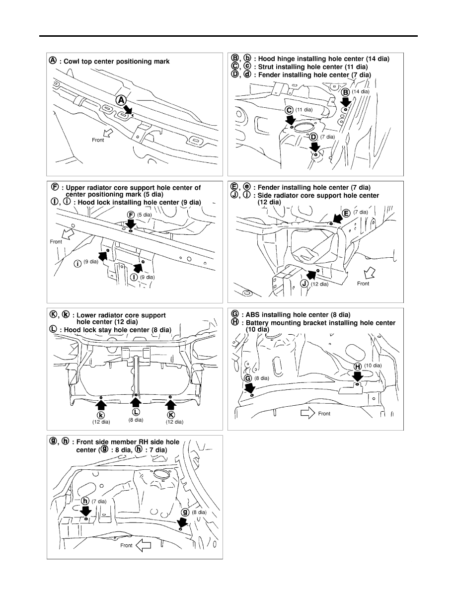
Measurement Points
NLBT0026S0102
NBT154
BODY (ALIGNMENT)
Alignment (Cont’d)
BT-66