Nissan Almera Tino V10. Manual - part 217
ATC-64
TROUBLE DIAGNOSIS
COMPONENT DESCRIPTION
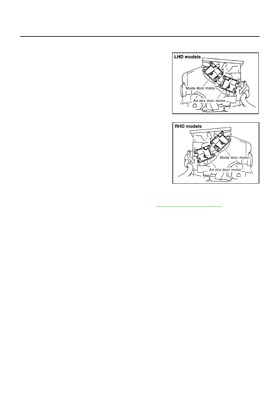
Air Mix Door Motor
The air mix door motor is attached to the heater & cooling unit. It
rotates so that the air mix door is opened or closed to a position set
by the auto amplifier. The air mix door position is then fed back to the
auto amplifier by PBR built-in air mix door motor.
DIAGNOSTIC PROCEDURE FOR AIR MIX DOOR MOTOR
SYMPTOM: Discharge air temperature does not change.
Perform diagnostic procedure for LAN system circuit. Refer to
.
RJIA0774E
RJIA0775E