Nissan Almera Tino V10. Manual - part 133


  Index      Nissan     Nissan Almera Tino V10 - Service Manual (2003 year)


Search            


Content   ..  131  132  133  134   ..


Nissan Almera Tino V10. Manual - part 133


AT-256

[EXC.F/EURO-OBD]

ON BOARD DIAGNOSTIC SYSTEM DESCRIPTION
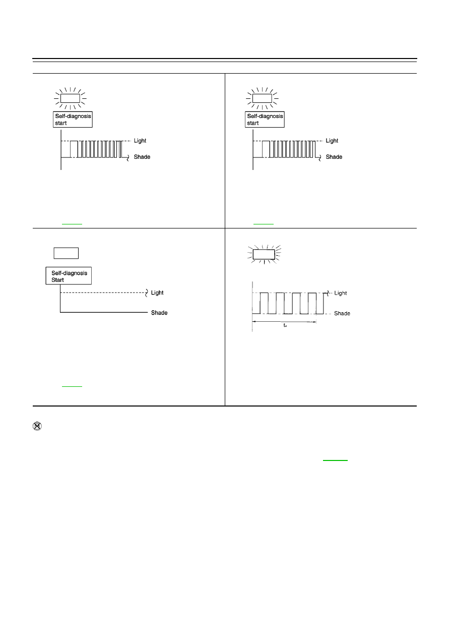
t

1

= 2.5 seconds

t

2

= 2.0 seconds

t

3

= 1.0 second

t

4

= 1.0 second

HOW TO ERASE SELF-DIAGNOSTIC RESULTS (WITHOUT CONSULT-II)

1.

If the ignition switch stays “ON” after repair work, be sure to turn ignition switch “OFF” once. Wait for at
least 3 seconds and then turn it “ON” again.

2.

Perform “SELF-DIAGNOSTIC PROCEDURE (Without CONSULT-II)”. Refer to

AT-252

.

3.

Turn ignition switch “OFF”. (The self-diagnostic results will be erased.)

10th judgement flicker is longer than others.

Line pressure solenoid valve circuit is short-circuited or discon-
nected.

Þ

Go to LINE PRESSURE SOLENOID VALVE.

Refer to

AT-392

11th judgement flicker is longer than others.

The ECM-A/T communication line is open or shorted.

Þ

Go to CAN COMMUNICATION LINE.

Refer to

AT-399

Lamp comes OFF.

PNP switch, overdrive control switch or throttle position switch cir-
cuit is disconnected or TCM is damaged.

Þ

Go to 21. TCM Self-diagnosis Does Not Activate (PNP &

Overdrive Control Switches, and Throttle Position Sensor).
Refer to

AT-337

Flickers as shown below.

Battery power is low.
Battery has been disconnected for a long time.
Battery is connected conversely.
(When reconnecting TCM connectors.—This is a problem.)

O/D OFF indicator lamp:

SCIA0704E

SCIA0705E

SCIA0706E

SAT804H

TROUBLE DIAGNOSIS — INTRODUCTION

AT-257

[EXC.F/EURO-OBD]

D

E

F

G

H

I

J

K

L

M

A

B

AT

TROUBLE DIAGNOSIS — INTRODUCTION

PFP:00000

Introduction

ECS0099W

The TCM receives a signal from the vehicle speed sensor, throttle
position sensor or PNP switch and provides shift control or lock-up
control via A/T solenoid valves.
Input and output signals must always be correct and stable in the
operation of the A/T system. The A/T system must be in good oper-
ating condition and be free of valve seizure, solenoid valve malfunc-
tion, etc.
It is much more difficult to diagnose a problem that occurs intermit-
tently rather than continuously. Most intermittent problems are
caused by poor electric connections or improper wiring. In this case,
careful checking of suspected circuits may help prevent the replace-
ment of good parts.
A visual check only, may not find the cause of the problems. A road
test with CONSULT-II or a circuit tester connected should be per-
formed. Follow the “Work Flow”. Refer to

AT-261, "Work Flow"

.

Before undertaking actual checks, take a few minutes to talk with a
customer who approaches with a drive ability complaint. The cus-
tomer can supply good information about such problems, especially
intermittent ones. Find out what symptoms are present and under
what conditions they occur. A “Diagnostic Worksheet” like the exam-
ple (

AT-258, "DIAGNOSTIC WORKSHEET"

) should be used.

Start your diagnosis by looking for “conventional” problems first. This
will help troubleshoot drive ability problems on an electronically con-
trolled engine vehicle.
Also check related Service bulletins for information.

SAT631IA

SAT632I

SEF234G

AT-258

[EXC.F/EURO-OBD]

TROUBLE DIAGNOSIS — INTRODUCTION

DIAGNOSTIC WORKSHEET
Information from Customer

KEY POINTS

WHAT..... Vehicle & A/T model

WHEN..... Date, Frequencies

WHERE..... Road conditions

HOW..... Operating conditions, Symptoms

Customer name

MR/MS

Model & Year

VIN

Trans. model

Engine

Mileage

Incident Date

Manuf. Date

In Service Date

Frequency

Continuous

Intermittent (

times a day)

Symptoms

Vehicle does not move.

(

Any position

Particular position)

No up-shift

(

1st

2nd

2nd

3rd

3rd

O/D)

No down-shift

(

O/D

3rd

3rd

2nd

2nd

1st)

Lockup malfunction

Shift point too high or too low.

Shift shock or slip

(

N

D

Lockup

Any drive position)

Noise or vibration

No kick down

No pattern select

Others

(

)

O/D OFF indicator lamp

Blinks for about 8 seconds.

Continuously lit

Not lit

TROUBLE DIAGNOSIS — INTRODUCTION

AT-259

[EXC.F/EURO-OBD]

D

E

F

G

H

I

J

K

L

M

A

B

AT

Diagnostic Worksheet

1.

Read the Fail-safe and listen to customer complaints.

AT-258,
"Information
from Cus-
tomer"

2.

CHECK A/T FLUID

AT-263, "A/T
Fluid Check"

Leakage (Follow specified procedure)

Fluid condition

Fluid level

3.

Perform STALL TEST and LINE PRESSURE TEST.

AT-264, "Stall
Test"

,

AT-267, "Line
Pressure
Test"

Stall test — Mark possible damaged components/others.

Torque converter one-way clutch

Reverse clutch

Forward clutch

Overrun clutch

Forward one-way clutch

Low & reverse brake

Low one-way clutch

Engine

Line pressure is low

Clutches and brakes except high clutch and

brake band are OK

Line Pressure test — Suspected parts:

4.

Perform all ROAD TEST and mark required procedures.

AT-268,
"Road Test"

4-
1.

Check before engine is started.

AT-270, "1.
CHECK
BEFORE
ENGINE IS
STARTED"

SELF-DIAGNOSTIC CONFIRMATION PROCEDURE — Mark detected items.

Vehicle speed sensor·A/T (Revolution sensor),

AT-347

.

Vehicle speed sensor·MTR,

AT-352

.

Accelerator pedal position (APP) sensor,

AT-356

.

Shift solenoid valve A,

AT-361

.

Shift solenoid valve B,

AT-366

.

Overrun clutch solenoid valve,

AT-371

.

Torque converter clutch solenoid valve,

AT-376

.

A/T fluid temperature sensor and TCM power source,

AT-381

.

Engine speed signal,

AT-387

.

Line pressure solenoid valve,

AT-392

.

CAN communication line,

AT-399

.

Control unit (RAM), control unit (ROM),

AT-207

.

Control unit (EEP ROM),

AT-209

.

PNP & overdrive control switches, and throttle position sensor,

AT-337

.

Battery

Others

4-
2.

Check at idle

AT-271, "2.
CHECK AT
IDLE"

1. O/D OFF Indicator Lamp Does Not Come On,

AT-312

.

2. Engine Cannot Be Started In “P” And “N” Position,

AT-313

.

3. In “P” Position, Vehicle Moves Forward Or Backward When Pushed,

AT-313

.

4. In “N” Position, Vehicle Moves,

AT-315

.

5. Large Shock. “N”

“R” Position,

AT-316

.

6. Vehicle Does Not Creep Backward In “R” Position,

AT-317

.

7. Vehicle Does Not Creep Forward In “D”, “2” Or “1” Position,

AT-320

.


Content   ..  131  132  133  134   ..