Nissan Almera Tino V10. Manual - part 79


  Index      Nissan     Nissan Almera Tino V10 - Service Manual (2003 year)


Search            


Content   ..  77  78  79  80   ..


Nissan Almera Tino V10. Manual - part 79


AT-40

[EURO-OBD]

ON BOARD DIAGNOSTIC SYSTEM DESCRIPTION

7.

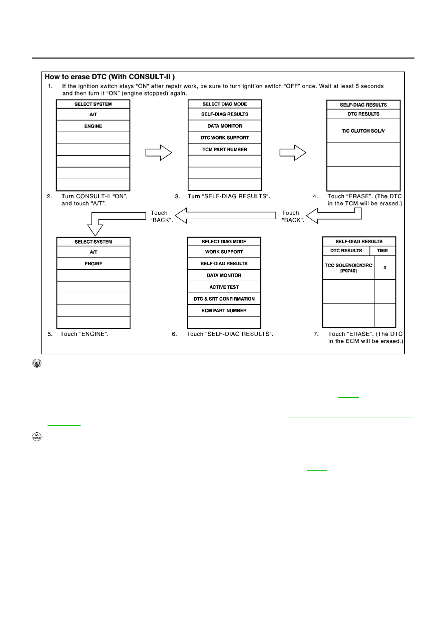
Touch “ERASE”. (The DTC in the ECM will be erased.)

HOW TO ERASE DTC (WITH GST)

1.

If the ignition switch stays “ON” after repair work, be sure to turn ignition switch “OFF” once. Wait at least
5 seconds and then turn it “ON” (engine stopped) again.

2.

Perform “EURO-OBD SELF-DIAGNOSTIC PROCEDURE (No Tools)”. Refer to

AT-50

. (The engine

warm-up step can be skipped when performing the diagnosis only to erase the DTC.)

3.

Select Mode 4 with Generic Scan Tool (GST). For details, refer to

EC-127, "Generic Scan Tool (GST)

Function"

.

HOW TO ERASE DTC (NO TOOLS)

1.

If the ignition switch stays “ON” after repair work, be sure to turn ignition switch “OFF” once. Wait at least
5 seconds and then turn it “ON” (engine stopped) again.

2.

Perform “TCM SELF-DIAGNOSTIC PROCEDURE (No Tools)”. Refer to

AT-51

. (The engine warm-up

step can be skipped when performing the diagnosis only to erase the DTC.)

SAT017K

ON BOARD DIAGNOSTIC SYSTEM DESCRIPTION

AT-41

[EURO-OBD]

D

E

F

G

H

I

J

K

L

M

A

B

AT

Malfunction Indicator (MI)

ECS0096Y

1.

The malfunction indicator lamp will light up when the ignition
switch is turned ON without the engine running. This is for
checking the lamp.

If the malfunction indicator does not light up, refer to

EC-545,

"MI & DATA LINK CONNECTORS"

.

(Or see MI & CONSULT-II in EC section. Refer to

EC-70,

"Malfunction Indicator (MI)"

,

EC-116, "CONSULT-II Function"

.

2.

When the engine is started, the malfunction indicator should
turned OFF.
If the lamp remains ON, the on board diagnostic system has
detected an emission-related (EURO-OBD) malfunction. For
detail, refer to

EC-54, "ON BOARD DIAGNOSTIC (OBD) SYSTEM"

.

CONSULT-II

ECS0096Z

After performing “SELF-DIAGNOSTIC PROCEDURE (WITH CONSULT-II)”

AT-41

, place check marks for

results on the “DIAGNOSTIC WORKSHEET”,

AT-57

. Reference pages are provided following the items.

NOTICE:
1.

The CONSULT-II electrically displays shift timing and lock-up timing (that is, operation timing of each sole-
noid valve).
Check for time difference between actual shift timing and the CONSULT-II display. If the difference is
noticeable, mechanical parts (except solenoid valves, sensors, etc.) may be malfunctioning. Check
mechanical parts using applicable diagnostic procedures.

2.

Shift schedule (which implies gear position) displayed on CONSULT-II and that indicated in Service Man-
ual may differ slightly. This occurs because of the following reasons:

Actual shift schedule has more or less tolerance or allowance,

Shift schedule indicated in Service Manual refers to the point where shifts start, and

Gear position displayed on CONSULT-II indicates the point where shifts are completed.

3.

Shift solenoid valve “A” or “B” is displayed on CONSULT-II at the start of shifting. Gear position is dis-
played upon completion of shifting (which is computed by TCM).

4.

Additional CONSULT-II information can be found in the Operation Manual supplied with the CONSULT-II
unit.

SELF-DIAGNOSTIC PROCEDURE (WITH CONSULT-II)

1.

Turn on CONSULT-II and touch “ENGINE” for EURO-OBD
detected items or touch “A/T” for TCM self-diagnosis.
If A/T is not displayed, check TCM power supply and ground cir-
cuit. Refer to

AT-107, "TCM Terminals and Reference Value"

. If

result is NG, refer to EL-11, ”Power Supply Routing”.

SAT652J

SAT014K

AT-42

[EURO-OBD]

ON BOARD DIAGNOSTIC SYSTEM DESCRIPTION

2.

Touch “SELF DIAGNOSIS”.
Display shows malfunction experienced since the last erasing
operation.
CONSULT-II performs “real time diagnosis”.
Also, any malfunction detected while in this mode will be dis-
played at real time.

SELF-DIAGNOSTIC RESULT TEST MODE

SAT987J

Detected items
(Screen terms for CONSULT-II, “SELF
DIAGNOSIS” test mode)

Malfunction is detected when...

TCM self-diagnosis

EURO-OBD (DTC)

Available by O/D OFF

indicator lamp or “A/T”

on CONSULT-II

Available by malfunc-

tion indicator*

2

,

“ENGINE” on CON-

SULT-II or GST

“A/T”

“ENGINE”

Park/neutral position (PNP) switch circuit

TCM does not receive the correct
voltage signal (based on the gear
position) from the switch.

P0705

PNP SW/CIRC

Revolution sensor

TCM does not receive the proper
voltage signal from the sensor.

X

P0720

VHCL SPEED
SEN·A/T

VEH SPD SEN/CIR
AT

Vehicle speed sensor (Meter)

TCM does not receive the proper
voltage signal from the sensor.

X

VHCL SPEED
SEN·MTR

A/T 1st gear function

A/T cannot be shifted to the 1st
gear position even if electrical cir-
cuit is good.

P0731*

1

A/T 1ST GR FNCTN

A/T 2nd gear function

A/T cannot be shifted to the 2nd
gear position even if electrical cir-
cuit is good.

P0732*

1

A/T 2ND GR FNCTN

A/T 3rd gear function

A/T cannot be shifted to the 3rd
gear position even if electrical cir-
cuit is good.

P0733*

1

A/T 3RD GR FNCTN

A/T 4th gear function

A/T cannot be shifted to the 4th
gear position even if electrical cir-
cuit is good.

P0734*

1

A/T 4TH GR FNCTN

Shift solenoid valve A

TCM detects an improper voltage
drop when it tries to operate the
solenoid valve.

X

P0750

SHIFT SOLENOID/V
A

SFT SOL A/CIRC

Shift solenoid valve B

TCM detects an improper voltage
drop when it tries to operate the
solenoid valve.

X

P0755

SHIFT SOLENOID/V
B

SFT SOL B/CIRC

Overrun clutch solenoid valve

TCM detects an improper voltage
drop when it tries to operate the
solenoid valve.

X

P1760

OVERRUN CLUTCH
S/V

O/R CLUCH SOL/
CIRC

T/C clutch solenoid valve

TCM detects an improper voltage
drop when it tries to operate the
solenoid valve.

X

P0740

T/C CLUTCH SOL/V

TCC SOLENOID/
CIRC

ON BOARD DIAGNOSTIC SYSTEM DESCRIPTION

AT-43

[EURO-OBD]

D

E

F

G

H

I

J

K

L

M

A

B

AT

X: Applicable
—: Not applicable
*1: These malfunctions cannot be displayed by MI if another malfunction is assigned to lamp MI.
*2: Refer to

AT-41, "Malfunction Indicator (MI)"

.

*3: A/T COMM LINE means CAN COMM LINE in this model.

Line pressure solenoid valve

TCM detects an improper voltage
drop when it tries to operate the
solenoid valve.

X

P0745

LINE PRESSURE S/
V

L/PRESS SOL/CIRC

Throttle position sensor (Accelerator Pedal
Position (APP) sensor)

TCM receives an excessively low
or high voltage from the sensor.

X

P1705

THROTTLE POSI
SEN

TP SEN/CIRC A/T

Engine speed signal

TCM does not receive the proper
voltage signal from the ECM.

X

P0725

ENGINE SPEED SIG

A/T fluid temperature sensor

TCM receives an excessively low
or high voltage from the sensor.

X

P0710

BATT/FLUID TEMP
SEN

ATF TEMP SEN/
CIRC

Engine control

The ECM-A/T communication line
is open or shorted.

X

U1000

A/T COMM LINE

*3

TCM (RAM)

TCM memory (RAM) is malfunc-
tioning.

CONTROL UNIT
(RAM)

TCM (ROM)

TCM memory (ROM) is malfunc-
tioning.

CONTROL UNIT
(ROM)

TCM (EEP ROM)

TCM memory (EEP ROM) is mal-
functioning.

CONT UNIT (EEP
ROM)

Initial start

This is not a malfunction message
(Whenever shutting off a power
supply to the TCM, this message
appears on the screen.)

X

INITIAL START

No failure
(NO SELF DIAGNOSTIC FAILURE INDI-
CATED FURTHER TESTING MAY BE
REQUIRED**)

No failure has been detected.

X

X

Detected items
(Screen terms for CONSULT-II, “SELF
DIAGNOSIS” test mode)

Malfunction is detected when...

TCM self-diagnosis

EURO-OBD (DTC)

Available by O/D OFF

indicator lamp or “A/T”

on CONSULT-II

Available by malfunc-

tion indicator*

2

,

“ENGINE” on CON-

SULT-II or GST

“A/T”

“ENGINE”


Content   ..  77  78  79  80   ..