Nissan Almera Tino V10. Manual - part 23
SFE641A
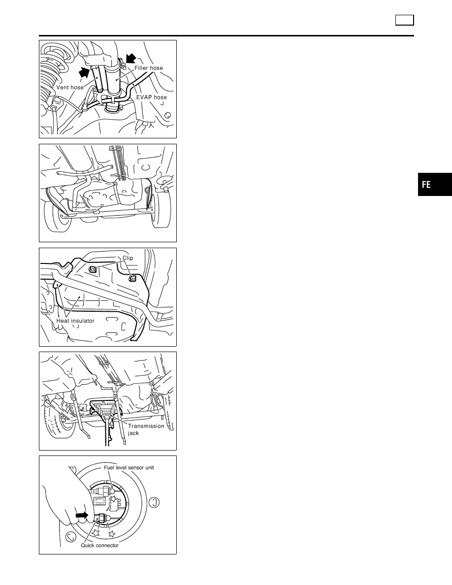
8.
From rear left area of fuel tank, remove filler hose, vent hose,
and EVAP hose.
CAUTION:
To prevent fuel from flowing out, install a blind cap immedi-
ately after the fuel hose is disconnected.
SFE642A
9.
Remove exhaust center tube.
SFE643A
10. Remove heat insulators from fuel tank side.
SFE644A
11. Set a suitable transmission jack under fuel tank.
12. Remove fuel tank mounting band bolts while supporting fuel
tank.
13. Remove fuel tank.
NFE072
INSTALLATION
NLFE0016S02
To install, reverse the removal procedure. Connect the quick con-
nector as follows:
I
Insert tube into the center of the connector until you hear a
click.
GI
MA
EM
LC
EC
CL
MT
AT
AX
SU
BR
ST
RS
BT
HA
SC
EL
IDX
FUEL SYSTEM
YD
Fuel Tank (Cont’d)
FE-21