Nissan GT-R (2007-2014 year). SECURITY CONTROL SYSTEM / SRS AIRBAG. Service Manual - part 3
VEHICLE SECURITY SYSTEM
SEC-33
< DTC/CIRCUIT DIAGNOSIS >
[INTELLIGENT KEY SYSTEM]
C
D
E
F
G
H
I
J
L
M
A
B
SEC
N
O
P
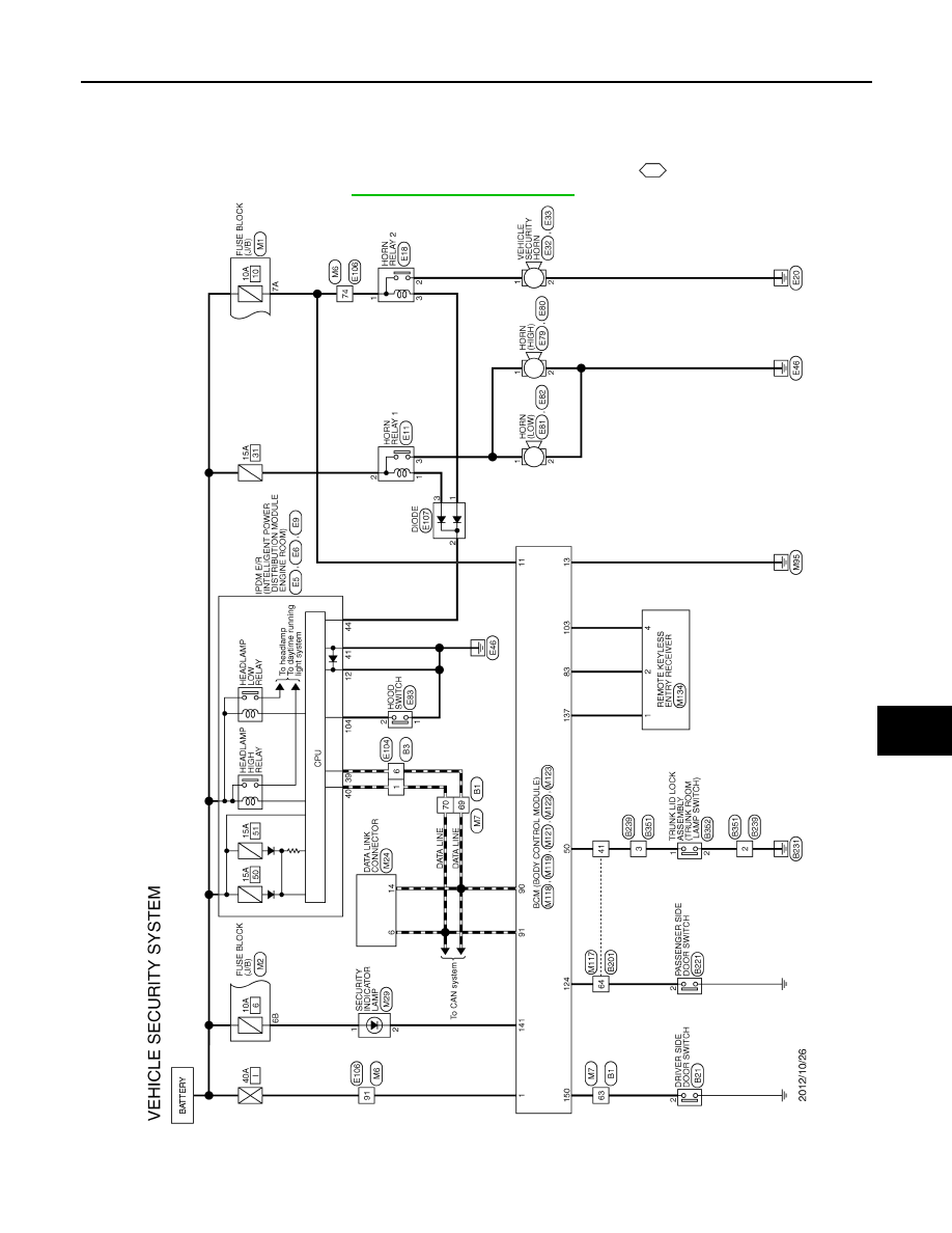
VEHICLE SECURITY SYSTEM
Wiring Diagram - VEHICLE SECURITY SYSTEM -
INFOID:0000000009163777
For connector terminal arrangements, harness layouts, and alphabets in a
(option abbreviation; if not
described in wiring diagram), refer to
GI-12, "Connector Information"
JRKWC2675GB
2014 GT-R