Nissan GT-R (2007-2014 year). EXTERIOR / FRONT AXLE / FUEL SYSTEM. Service Manual - part 2


  Index      Manuals     Nissan GT-R (2007-2014 year). EXTERIOR / FRONT AXLE / FUEL SYSTEM. Service Manual


Search            copyright infringement  


Content      ..      1      2      3      ..


Nissan GT-R (2007-2014 year). EXTERIOR / FRONT AXLE / FUEL SYSTEM. Service Manual - part 2


FRONT BUMPER

EXT-17

< REMOVAL AND INSTALLATION >

C

D

E

F

G

H

I

J

L

M

A

B

EXT

N

O

P

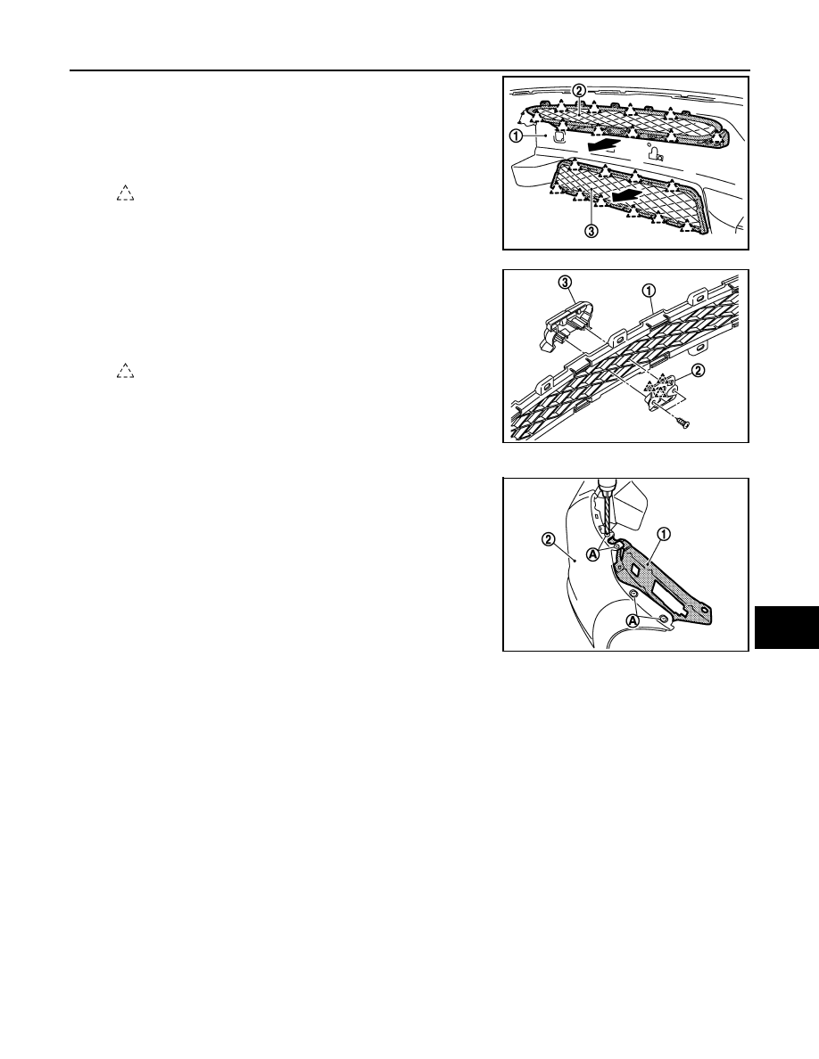
• Front bumper finisher B

Disengage the pawls from the back of the bumper fascia (1),
and then remove the front bumper finisher B (2). 

• Front bumper grille

Disengage the pawls from the back of the bumper fascia, and
then remove the front bumper grille (3). 

• Front emblem

Remove the mounting screws, and then remove the front
emblem (3) from the front bumper finisher B (1). 
Disengage pawls, and then remove the front emblem bracket
(2). 

• Disengage the mounting screws and pawls, and then remove the front emblem. 
• Bumper side bracket (LH/RH).

Remove the rivet (A), and then remove the bumper side
bracket (1) from the bumper fascia (2). 

NOTE:
Removal and installation of rivet

: Pawl

NNKIA1692ZZ

: Pawl

NNKIA0215ZZ

NNKIA1694ZZ

Revision: 2012 November

2014 GT-R

EXT-18

< REMOVAL AND INSTALLATION >

FRONT BUMPER

• Grind the head of rivet (1) with a drill (A) [bit of 

φ

 4.0 – 4.5 mm

(

φ

 0.157 – 0.177 in)], and then remove the bumper side

bracket. 

• Securely crimp the bumper side bracket with the bumper fas-

cia using a hand riveter (B). 

13. Remove the energy absorber. 

14. Remove the mounting bolts (A) and (B), and then remove the

bumper brackets (1) (LH/RH). 

15. Remove the mounting bolts, and then remove the bumper reinforcement with power tool. 

INSTALLATION

Note the following, and install in the reverse order of removal.

If front bumper fascia is replaced with new one, install blind nut following the steps as below.

1.

Make a hole in the front bumper fascia with drill, shown in the figure.

Bumper side bracket

Crimping thickness

: 1.2 – 6.4 mm (0.047 – 0.252 in)

Prepared hole diameter

φ

 4.1 –

φ

 4.4 mm (0.161 – 0.173 in)

Used rivet head diameter : 

φ

 8.0 mm (0.315 in)

NNKIA0122ZZ

NNKIA1693ZZ

Dimension

A: Distance from vehicle center

: 88.9 mm (3.500 in)

B: Distance from edge

: 41.6 mm (1.638 in)

C: Hole size

φ

 9.7 mm (0.382 in)

JMKIA2995ZZ

Revision: 2012 November

2014 GT-R

FRONT BUMPER

EXT-19

< REMOVAL AND INSTALLATION >

C

D

E

F

G

H

I

J

L

M

A

B

EXT

N

O

P

2.

Insert blind nut (A) to hand nut rivet setter (B).

3.

Set blind nut with hand nut rivet setter (A).

CAUTION:

Tighten the bumper brackets (LH/RH) and the bumper reinforcement after installing the engine under-
cover because the structure is so designed not to have any dimensional fluctuation between bumper
reinforcement and engine under cover.   
NOTE:
Clearance between front bumper and each unit. 

JMKIA2996ZZ

JMKIA2997ZZ

JMKIA3006ZZ

Portion

Clearance

Surface height difference 

Front bumper and hood

A – A 1.5 – 5.5 mm (0.059 – 0.217 in)

2.0 – 0.0 mm (

0.079 – 0.000 in)

Front bumper and head lamp

B – B 0.5 – 3.5 mm (0.020 – 0.138 in)

Front bumper and front fender C – C 0.0 – 0.8 mm (0.000 – 0.031 in)

0.2 – 1.8 mm (

0.008 – 0.071 in)

Front bumper and engine un-
dercover

D – D 0.0 – 1.0 mm (0.000 – 0.039 in)

1.0 – 1.0 mm (

0.039 – 0.039 in)

Revision: 2012 November

2014 GT-R

EXT-20

< REMOVAL AND INSTALLATION >

REAR BUMPER

REAR BUMPER

Exploded View

INFOID:0000000009161555

1.

Bumper fascia

2.

Energy absorber

3.

Bumper reinforcement

4.

Bumper stay RH

5.

Bumper side bracket B RH

6.

Bumper side bracket A RH

7.

Rear bumper upper frame RH

8.

Rear bumper upper frame LH

9.

Bumper side bracket A LH

JMKIA2775ZZ

Revision: 2012 November

2014 GT-R

REAR BUMPER

EXT-21

< REMOVAL AND INSTALLATION >

C

D

E

F

G

H

I

J

L

M

A

B

EXT

N

O

P

Removal and Installation

INFOID:0000000009161556

CAUTION:

• Be careful of being burned because the rear bumper guard is very hot after driving. 
• The bumper fascia is made of resin. Never apply strong force to it, and be careful to prevent contact

with oil. 

REMOVAL

1.

Open trunk lid.

2.

Remove the trunk floor carpet, trunk rear finisher and rear wheel house finishers (LH/RH). Refer to 

INT-

27, "Removal and Installation"

3.

Remove the mounting nuts (A) of rear combination lamps (1)
(LH/RH).

4.

Disconnect the harness connector (B) and remove the harness
grommet (C) from the rear combination lamps (LH/RH).

5.

Remove the mounting nuts (A) of the side marker lens (1) (LH/
RH).

6.

Remove the clips (A) from the lower surface of bumper fascia. 

10. Bumper side bracket B LH

11.

Bumper stay LH

12. Rear emblem

13. Rear combination lamp RH

14. Rear combination lamp LH

15. Side marker lens LH

16. Rear bumper side frame B LH

17. Bumper side bracket C LH

18. Rear bumper guard LH

19. Bumper fascia (lower)

20. Bumper side bracket C RH

21. Rear bumper side frame B RH

22. Rear bumper side frame A RH

23. License lamp bracket

24. Rear bumper side frame A LH

25. Side marker lens RH

26. Bumper finisher

27. Rear bumper guard RH

28. J-nut

Refer to 

GI-4, "Components"

 for symbols in the figure. 

NNKIA0111ZZ

NNKIA0112ZZ

NNKIA0113ZZ

Revision: 2012 November

2014 GT-R

EXT-22

< REMOVAL AND INSTALLATION >

REAR BUMPER

7.

Remove the clips (A) of the rear wheel house protector (1) (LH/
RH).

8.

Pull off the rear wheel house protector to secure work space,
and then remove the screws (A) and the nuts (B) connecting the
bumper fascia and the rear fender (LH/RH).

9.

Remove the clips connecting the bumper side bracket C (1) and
the bumper fascia (LH/RH).

10. Pull the bumper fascia in the direction and in the order 1 - 3 as

shown in the figure while lifting up both ends, and then disen-
gage it from the bumper side bracket. 

CAUTION:

Never damage the tabs integrated with the bumper fascia
and bumper side bracket during removal. 

11. Pull the bumper fascia toward the rear of the vehicle, and then disengage it from the rear bumper upper

frame (LH/RH). 

NNKIA0114ZZ

NNKIA0115ZZ

NNKIA0217ZZ

: Pawl

NNKIA0117ZZ

Revision: 2012 November

2014 GT-R

REAR BUMPER

EXT-23

< REMOVAL AND INSTALLATION >

C

D

E

F

G

H

I

J

L

M

A

B

EXT

N

O

P

12. Pull the bumper fascia toward the rear of the vehicle, and then

disconnect the license lamp connector (A). 

13. Remove the bumper fascia. 

CAUTION:

When removing bumper fascia, 2 workers are required so as to prevent it from dropping. 

14. Remove the following parts after removing the bumper fascia. 

• Rear combination lamp (LH/RH)

Remove the mounting screws, and then remove the rear com-
bination lamp (2) from the bumper fascia (1). 

• Side marker lens (LH/RH)

Remove the mounting bolts and clip, and then remove the side
marker lens (3) from the bumper fascia. 

• Bumper fascia (lower)

Disengage the clips and pawls, and then remove the bumper
fascia (lower) (2) from the bumper fascia (1). 

• Bumper finisher

Disengage the pawls, and then remove the bumper finisher (3)
from the bumper fascia (lower). 

• License lamp bracket

Remove the mounting screws, and then remove the license
lamp bracket (2) from the bumper fascia (1). 

NNKIA0118ZZ

NNKIA0119ZZ

: Pawl

NNKIA0120ZZ

NNKIA0123ZZ

Revision: 2012 November

2014 GT-R

EXT-24

< REMOVAL AND INSTALLATION >

REAR BUMPER

• Rear bumper side frame (LH/RH)

Remove the rivets (3), and then remove the rear bumper side
frame (2) from the bumper fascia (1). 

• Rear bumper guard (LH/RH)

Remove the rivets (6), and then remove the rear bumper
guard (5) from the bumper fascia (lower) (4). 

NOTE:
Removal and installation of rivet
• Grind the head of rivet (1) with a drill (A) [bit of 

φ

4.0 – 4.5 mm

(

φ

0.157 – 0.177 in)], and then remove the bumper side

bracket. 

• Securely crimp the bumper side bracket with the bumper

fascia using a hand riveter (B). 

15. Remove the energy absorber. 

16. Remove the mount rubber that is hanged from the bracket attached to the bumper reinforcement. 
17. Remove the harness clamp of the license lamp harness from the bumper reinforcement. 

18. Remove the mounting nuts, and then remove the bumper reinforcement. 

INSTALLATION

Install in the reverse order of removal.
NOTE:

:Vehicle front

NNKIA0121ZZ

Rear bumper side frame LH/RH

Crimping thickness

: 4.0 – 8.0 mm (0.157 – 0.315 in)

Prepared hole diameter

φ

 3.2 mm (0.126 in)

Used rivet head diameter

φ

 8.0 mm (0.315 in)

Rear bumper guard LH/RH

Crimping thickness

: 1.2 – 6.4 mm (0.047 – 0.252 in)

Prepared hole diameter

φ

 4.1 –

φ

4.4 mm (0.161 – 0.173 in)

Used rivet head diameter

φ

 8.0 mm (0.315 in)

NNKIA0122ZZ

Revision: 2012 November

2014 GT-R

REAR BUMPER

EXT-25

< REMOVAL AND INSTALLATION >

C

D

E

F

G

H

I

J

L

M

A

B

EXT

N

O

P

Clearance between rear bumper and each unit. 

NNKIA0124ZZ

Portion

Clearance

Surface height difference

Rear bumper and rear fender A – A 0.0 – 0.8 mm (0.000 – 0.031 in)

1.8 – 0.2 mm (

0.071 – 0.008 in)

Rear bumper and trunk lid

B – B 2.0 – 6.0 mm (0.079 – 0.236 in)

2.0 – 1.0 mm (

0.079 – 0.039 in)

Rear bumper and trunk lid

C – C 2.5 – 6.5 mm (0.098 – 0.256 in)

1.9 – 1.9 mm (

0.075 – 0.075 in)

Rear bumper and trunk lid

D – D 4.0 – 8.0 mm (0.157 – 0.315 in)

Revision: 2012 November

2014 GT-R

EXT-26

< REMOVAL AND INSTALLATION >

COWL TOP

COWL TOP

Exploded View

INFOID:0000000009161557

RHD models

JMKIA6704GB

1.

Wiper arm & blade RH

2.

Wiper arm cover RH

3.

Brake master cylinder cover

4.

Hoodledge cover RH

5.

Strut support bar

6.

Strut support bar bracket RH

7.

Cowl top cover seal

8.

Strut support bar bracket LH

9.

Hoodledge cover LH

10. Battery cover

11. Cowl top cover LH

12. Cowl top center stay

13. Cowl top cover seal

14. Wiper arm & blade LH

15. Wiper arm cover LH

16. Cowl top cover RH

17. Washer tube

18. EPT sealer

Revision: 2012 November

2014 GT-R

COWL TOP

EXT-27

< REMOVAL AND INSTALLATION >

C

D

E

F

G

H

I

J

L

M

A

B

EXT

N

O

P

Removal and Installation

INFOID:0000000009161558

REMOVAL

1.

Open hood.

2.

Remove the front wiper arms & blades (LH/RH). Refer to 

WW-21, "Removal and Installation"

3.

Disengage the clips with the remover tool (A), and then remove
the cowl top seal (1).

4.

Remove the battery cover and the brake master cylinder cover. 

5.

Remove the cowl top cover seal. 

6.

Remove the clips, and then remove the hood ledge cover (LH/RH). 

7.

Remove the clips from the cowl top cover (LH/RH). 

8.

Lift up the cowl top cover RH (1), and then pull it toward the front
of the vehicle. 

9.

Disengage the joint of washer tube on rear side of cowl top
cover RH, and then remove the cowl top cover RH. 

10. Push down the lever (A) (to disengage from the pin of wind-

shield), and then pull out the cowl top cover LH (1) toward the
front of the vehicle. 

11. Disengage the joint of the washer tube on the rear side of cowl

top cover LH and the joint of (B), and then remove the cowl top
cover LH. 

12. Remove the following parts after removing the cowl top cover. 

• Washer tube: Refer to 

WW-18, "Removal and Installation"

• EPT sealer

13. Remove mounting bolts of strut support bar and strut support bar bracket.
14. Remove mounting bolts of strut support bar and dash panel. Remove strut support bar.

15. Remove strut support bar bracket mounting nuts, and then remove strut support bar bracket.

INSTALLATION

Note the following, and install in the reverse order of removal.

19. Strut housing RH

20. Strut housing LH

Refer to 

GI-4, "Components"

 for symbols in the figure. 

: Clip

NNKIA0138ZZ

JMKIA2777ZZ

JMKIA2778ZZ

Revision: 2012 November

2014 GT-R

EXT-28

< REMOVAL AND INSTALLATION >

COWL TOP

CAUTION:

• Always install strut support bar with tires on level ground.
• When installing strut support bar bracket, always install in numerical order according to the follow-

ing.

- Temporarily tighten mounting bolt (A) to strut housing.
- Tighten mounting nuts (B) to shock absorber to the specified torque.
- Tighten mounting bolts (A) to strut housing to the specified torque.
• When removing strut support bar mounting bolts, check bolts and washers for damage of surface

treatment and for white corrosion to prevent electric corrosion.

• Washer, even if its surface treatment is damaged, is reusable when touch-up paint is applied to

washer contact surface. Never reuse part when white corrosion is found.

• During the first special inspection [After 2,000 km (1,000 miles)], be sure to perform additional tight-

ening in accordance with the specified torque for the nuts (each one on the left and right sides) that
jointly tighten the strut support bar mounting bracket and the shock absorber. Also, perform addi-
tional tightening of the nuts in accordance with the specified torque after driving 500 – 1,000 km (300
– 600 miles) when the strut support bar or shock absorber has been removed and installed.

• Clean the joint between the cowl top cover and the windshield, and then install them. 
• Replace the EPT sealer on the back surface with new EPT sealer when reusing the cowl top cover. 
• Remove the EPT sealer remaining on the cowl top cover using a double-faced adhesive tape

remover.

• To maintain adhesion, never wash the vehicle within 24 hours after installation. 
• Align concave of cowl top cover LH (1) to windshield glass pin

(A) as shown in the figure when installing.

• Perform the stop position adjustment at the installation of the front wiper arms. Refer to 

WW-22,

"Adjustment"

1.

Strut support bar bracket RH

2.

Strut support bar bracket LH

JMKIA7767ZZ

JMKIA2779ZZ

Revision: 2012 November

2014 GT-R

FENDER PROTECTOR

EXT-29

< REMOVAL AND INSTALLATION >

C

D

E

F

G

H

I

J

L

M

A

B

EXT

N

O

P

FENDER PROTECTOR

FENDER PROTECTOR

FENDER PROTECTOR : Exploded View

INFOID:0000000009161559

JMKIB1351ZZ

Revision: 2012 November

2014 GT-R

EXT-30

< REMOVAL AND INSTALLATION >

FENDER PROTECTOR

FENDER PROTECTOR : Removal and Installation

INFOID:0000000009161560

REMOVAL

1.

Remove the clip (A) from the front edge of the center mud
guard. 

2.

Remove the screws (A) connecting the fender protector (rear). 

3.

Remove the bolt (A) and the screw (B) on the center mud guard
lower surface. 

4.

Remove the clip of the fender protector (rear). 

5.

Remove the fender clips from wheel house arches, and then remove fender protector (rear) from wheel
house.

1.

Fender protector (front)

2.

Grommet

3.

Fender clip

4.

Fender protector (rear)

5.

J-nut

6.

Center mud guard

7.

Floor under cover

8.

Front under cover

9.

Engine under cover

: Vehicle front

NNKIA0129ZZ

JMKIB1366ZZ

NNKIA0131ZZ

Revision: 2012 November

2014 GT-R

FENDER PROTECTOR

EXT-31

< REMOVAL AND INSTALLATION >

C

D

E

F

G

H

I

J

L

M

A

B

EXT

N

O

P

6.

Remove the screw (A) connecting the fender protector (front). 

7.

Remove the clips of the fender protector (front). 

8.

Remove the fender clips from wheel house arches, and then remove fender protector (front) from wheel
house. 

9.

Remove the fender clips after removing the fender protector. 

INSTALLATION

Install in the reverse order of removal.

REAR WHEEL HOUSE PROTECTOR

REAR WHEEL HOUSE PROTECTOR : Exploded View

INFOID:0000000009161561

NNKIA0132ZZ

NNKIA0134GB

Revision: 2012 November

2014 GT-R

EXT-32

< REMOVAL AND INSTALLATION >

FENDER PROTECTOR

REAR WHEEL HOUSE PROTECTOR : Removal and Installation

INFOID:0000000009161562

REMOVAL

1.

Remove the bolts (A) and (B) tighten the rear diffuser together
with the rear of rear wheel house protector. 

2.

Remove the bolt (A) tighten the rear diffuser (2) together with the
front of rear wheel house protector (1). 

3.

Remove the clip (A) connecting the center mud guard with the
rear wheel house protector. 

4.

Remove the clips of rear wheel house protector, and then remove it from the wheel house. 

INSTALLATION

Note the following, and install in the reverse order of removal.

CAUTION:

• Replace the mounting bolts with new ones to prevent electric corrosion when removing the rear dif-

fuser mounting bolt.

• Tighten the bolts of the rear wheel house protector and the rear diffuser to the specified torque.

Refer to 

EXT-41, "REAR DIFFUSER : Exploded View"

1.

Rear wheel house protector

Refer to 

GI-4, "Components"

 for symbols shown the figure. 

NNKIA0137ZZ

NNKIA0136ZZ

NNKIA0135ZZ

Revision: 2012 November

2014 GT-R


Content      ..      1      2      3      ..