Nissan GT-R. Manual - part 328


  Главная      Nissan     Nissan GT-R (2007-2014 year) - Service Manual


поиск по сайту            


содержание   ..  326  327  328  329   ..


Nissan GT-R. Manual - part 328


WW-4

< SYSTEM DESCRIPTION >

FRONT WIPER AND WASHER SYSTEM

NOTE:
• BCM stops the transmitting of the front wiper request signal when the ignition switch OFF.
• IPDM E/R turns the front wiper relay OFF when the ignition switch OFF.

FRONT WIPER OPERATION LINKED WITH WASHER

• BCM transmits the front wiper request signal (LO) to IPDM E/R with CAN communication according to the

washer linked operating condition of the front wiper.

• BCM transmits the front wiper request signal (LO) so that the front wiper operates approximately 2 times

when the front washer switch OFF is detected.

Washer linked operating condition of front wiper

- Ignition switch ON
- Front washer switch ON (0.4 second or more)
• IPDM E/R turns ON the integrated front wiper relay according to the front wiper request signal (LO).
• The washer pump is grounded through the combination switch when the front washer switch ON.

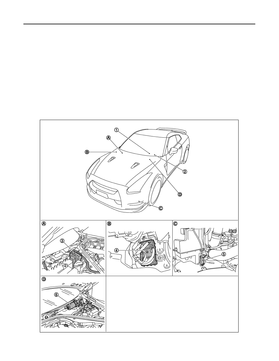
Component Parts Location

INFOID:0000000009161832

JPLIA1174ZZ

FRONT WIPER AND WASHER SYSTEM

WW-5

< SYSTEM DESCRIPTION >

C

D

E

F

G

H

I

J

K

M

A

B

WW

N

O

P

Component Description

INFOID:0000000009161833

1.

Combination switch

2.

Combination meter

3.

IPDM E/R

4.

BCM

5.

Washer pump

6.

Front wiper motor

A.

Engine room dash panel (RH)

B.

Dash side lower (Passenger side)

C.

Radiator core support (RH)

D.

Cowl top, left side of engine room

Part

Description

BCM

• Detects the each switch status by the combination switch reading function.
• Requests (with CAN communication) the front wiper relay and the front wiper high relay ON to 

IPDM E/R.

IPDM E/R

• Controls the integrated relay according to the request (with CAN communication) from BCM.
• Performs the auto stop control of the front wiper.

Combination switch
(Wiper & washer switch)

Refer to 

BCS-5, "System Description"

.

Combination meter

Transmits the vehicle speed signal to BCM with CAN communication.

WW-6

< SYSTEM DESCRIPTION >

DIAGNOSIS SYSTEM (IPDM E/R)

DIAGNOSIS SYSTEM (IPDM E/R)

Diagnosis Description

INFOID:0000000009161836

AUTO ACTIVE TEST

Description

In auto active test mode, the IPDM E/R sends a drive signal to the following systems to check their operation.
• Front wiper (LO, HI)
• Parking lamps
• License plate lamps
• Side marker lamps
• Tail lamps
• Headlamps (LO, HI)
• A/C compressor (magnet clutch)
• Cooling fan (cooling fan control module)

Operation Procedure

1.

Close the hood and lift the wiper arms from the windshield. (Prevent windshield damage due to wiper
operation)
NOTE:
When auto active test is performed with hood opened, sprinkle water on windshield beforehand.

2.

Turn the ignition switch OFF.

3.

Turn the ignition switch ON, and within 20 seconds, press the driver door switch 10 times. Then turn the
ignition switch OFF.

CAUTION:

Close passenger door.

4.

Turn the ignition switch ON within 10 seconds. After that the horn sounds once and the auto active test
starts.

5.

After a series of the following operations is repeated 3 times, auto active test is completed.

NOTE:
When auto active test mode has to be cancelled halfway through test, turn the ignition switch OFF.

CAUTION:

• If auto active test mode cannot be actuated, check door switch system. Refer to 

DLK-44,

"Component Function Check"

.

• Do not start the engine.

Inspection in Auto Active Test Mode

When auto active test mode is actuated, the following 5 steps are repeated 3 times.

*: Outputs duty ratio of 50% for 5 seconds 

 duty ratio of 100% for 5 seconds on the cooling fan control module.

Operation 
sequence

Inspection location

Operation

1

Front wiper

LO for 5 seconds 

 HI for 5 seconds

2

• Parking  lamps
• License plate lamps
• Side marker lamps
• Tail lamps

10 seconds

3

Headlamps

LO 

 HI 5 times

4

A/C compressor (magnet clutch)

ON 

 OFF 5 times

5

*

Cooling fan

MID for 5 seconds 

 HI for 5 seconds

DIAGNOSIS SYSTEM (IPDM E/R)

WW-7

< SYSTEM DESCRIPTION >

C

D

E

F

G

H

I

J

K

M

A

B

WW

N

O

P

Concept of auto active test

• IPDM E/R starts the auto active test with the door switch signals transmitted by BCM via CAN communica-

tion. Therefore, the CAN communication line between IPDM E/R and BCM is considered normal if the auto
active test starts successfully.

• The auto active test facilitates troubleshooting if any systems controlled by IPDM E/R cannot be operated.

Diagnosis chart in auto active test mode

NNMIA0051GB

Symptom

Inspection contents

Possible cause

Any of the following components do not operate

• Parking  lamps
• License plate lamps
• Side marker lamps
• Tail lamps
• Headlamp (HI, LO)
• Front wiper (HI, LO)

Perform auto active test.
Does the applicable system 
operate?

YES

BCM signal input circuit

NO

• Lamp or motor
• Lamp or motor ground circuit
• Harness or connector be-

tween IPDM E/R and appli-
cable system

• IPDM E/R

A/C compressor does not operate

Perform auto active test.
Does the magnet clutch oper-
ate?

YES

• A/C amp. signal input circuit
• CAN communication signal 

between A/C amp. and ECM

• CAN communication signal 

between ECM and IPDM E/R

NO

• Magnet clutch
• Harness or connector be-

tween IPDM E/R and magnet 
clutch

• IPDM E/R

Cooling fan does not operate

Perform auto active test.
Does the cooling fan operate?

YES

• ECM signal input circuit
• CAN communication signal 

between ECM and IPDM E/R

NO

• Cooling fan
• Harness or connector be-

tween cooling fan and cool-
ing fan control module

• Cooling fan control module
• Harness or connector be-

tween IPDM E/R and cooling 
fan control module

• Cooling fan relay
• Harness or connector be-

tween IPDM E/R and cooling 
fan relay

• IPDM E/R


содержание   ..  326  327  328  329   ..