Nissan GT-R. Manual - part 283


  Главная      Nissan     Nissan GT-R (2007-2014 year) - Service Manual


поиск по сайту            


содержание   ..  281  282  283  284   ..


Nissan GT-R. Manual - part 283


SEC-14

< SYSTEM DESCRIPTION >

[INTELLIGENT KEY SYSTEM]

VEHICLE SECURITY SYSTEM

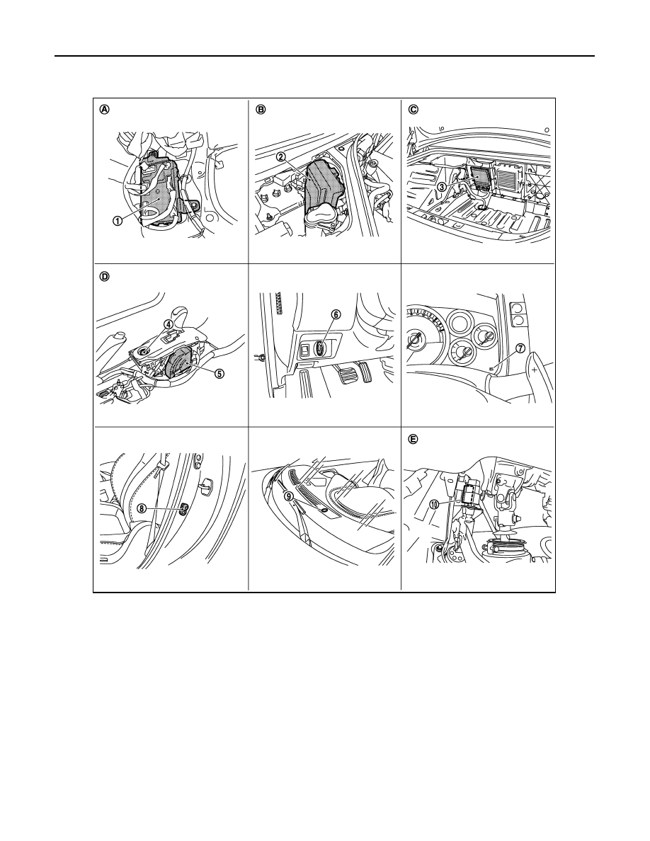
Component Parts Location

INFOID:0000000009163607

1.

BCM M118, M119, M121, M122, 
M123

2.

IPDM E/R E4, E5, E6, E7

3.

TCM B45

4.

Push-button ignition switch M131

5.

A/T shift selector (detention switch) 
B20

6.

Key slot M60

7.

Combination meter (Key warning 
lamp) M53

8.

Driver side door switch B21

9.

Security indicator lamp M29

10. Stop lamp switch E110

A.

Behind the instrument lower panel 
RH

B.

Engine room dash panel (RH)

C.

View with trunk front finisher re-
moved

D.

View with center console assembly 
removed

E.

View with instrument lower panel 
(driver) removed

JMKIA2909ZZ

VEHICLE SECURITY SYSTEM

SEC-15

< SYSTEM DESCRIPTION >

[INTELLIGENT KEY SYSTEM]

C

D

E

F

G

H

I

J

L

M

A

B

SEC

N

O

P

1.

Trunk lid lock assembly (trunk room 
lamp switch) B352

2.

Remote keyless entry receiver M134  3.

Inside key antenna (console) M146

4.

Inside key antenna (trunk room) B41 5.

Inside key antenna (instrument cen-
ter) M75

6.

Horn (high) E79, E80

7.

Horn (low) E81, E82

8.

Hood switch E83

9.

ECM M107

A.

View with trunk lid finisher removed

B.

Behind the display unit

C.

Back of the rear console assembly

D.

Behind the trunk front finisher

E.

Back of the cluster kid C (lower)

F.

Behind the front bumper

G.

Behind the instrument lower panel 
(assist)

JMKIA2910ZZ

SEC-16

< DTC/CIRCUIT DIAGNOSIS >

[INTELLIGENT KEY SYSTEM]

POWER SUPPLY AND GROUND CIRCUIT

DTC/CIRCUIT DIAGNOSIS

POWER SUPPLY AND GROUND CIRCUIT

BCM

BCM : Diagnosis Procedure

INFOID:0000000009163751

1.

CHECK FUSE AND FUSIBLE LINK

Check that the following fuse and fusible link are not blown.

Is the fuse fusing?

YES

>> Replace the blown fuse or fusible link after repairing the affected circuit if a fuse or fusible link is

blown.

NO

>> GO TO 2.

2.

CHECK POWER SUPPLY CIRCUIT

1.

Turn ignition switch OFF.

2.

Disconnect BCM connectors.

3.

Check voltage between BCM harness connector and ground.

Is the measurement value normal?

YES

>> GO TO 3.

NO

>> Repair harness or connector.

3.

CHECK GROUND CIRCUIT

Check continuity between BCM harness connector and ground.

Does continuity exist?

YES

>> INSPECTION END

NO

>> Repair harness or connector.

IPDM E/R

IPDM E/R : Diagnosis Procedure

INFOID:0000000009163752

1.

CHECK FUSES AND FUSIBLE LINK

Check that the following IPDM E/R fuses or fusible links are not blown.

Signal name

Fuse and fusible link No.

Battery power supply

I

10

Terminals

Voltage

(Approx.)

(+)

(

)

BCM

Ground

Connector

Terminal

M118

1

Battery voltage

M119

11

BCM

Ground

Continuity

Connector

Terminal

M119

13

Existed

POWER SUPPLY AND GROUND CIRCUIT

SEC-17

< DTC/CIRCUIT DIAGNOSIS >

[INTELLIGENT KEY SYSTEM]

C

D

E

F

G

H

I

J

L

M

A

B

SEC

N

O

P

Is the fuse fusing?

YES

>> Replace the blown fuse or fusible link after repairing the affected circuit if a fuse or fusible link is

blown.

NO

>> GO TO 2.

2.

CHECK POWER SUPPLY CIRCUIT

1.

Turn the ignition switch OFF.

2.

Disconnect IPDM E/R connector.

3.

Check voltage between the IPDM E/R harness connector and the ground.

Is the measurement value normal?

YES

>> GO TO 3.

NO

>> Repair the harness or connector.

3.

CHECK GROUND CIRCUIT

Check continuity between the IPDM E/R harness connectors and the ground.

Does continuity exist?

YES

>> INSPECTION END

NO

>> Repair the harness or connector.

Signal name

Fuses and fusible link No.

Battery power supply

C

50

51

Terminals

Voltage

(Approx.)

(+)

(

)

IPDM E/R

Connector

Terminal

Ground

E4

1

Battery voltage

IPDM E/R

Ground

Continuity

Connector

Terminal

E5

12

Existed

E6

41


содержание   ..  281  282  283  284   ..