Nissan GT-R. Manual - part 55


  Главная      Nissan     Nissan GT-R (2007-2014 year) - Service Manual


поиск по сайту            


содержание   ..  53  54  55  56   ..


Nissan GT-R. Manual - part 55


PRECAUTIONS

BR-5

< PRECAUTION >

C

D

E

G

H

I

J

K

L

M

A

B

BR

N

O

P

• After pressing the brake pedal more deeply or harder than normal driving, such as when air bleeding, check

each item of brake pedal. Adjust brake pedal if it is outside the standard condition. 

• Always clean with new brake fluid when cleaning the master cylinder, brake caliper and other components.
• Never use mineral oils such as gasoline or light oil to clean. They may damage rubber parts and cause a

malfunction.

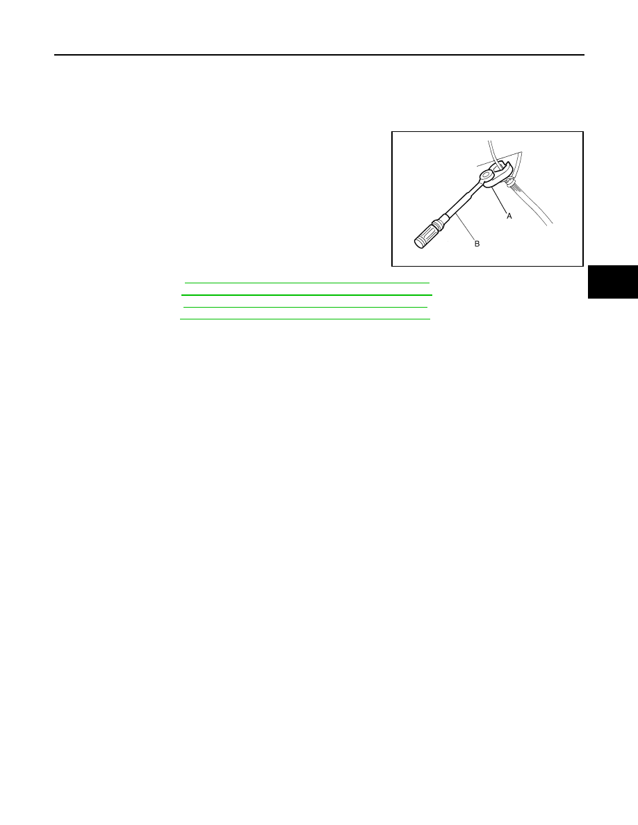
• Always loosen the brake tube flare nut with a flare nut wrench.
• Tighten the brake tube flare nut to the specified torque with a crow-

foot (A) and torque wrench (B).

• Always confirm the specified tightening torque when installing the

brake pipes.

• Turn the ignition switch OFF and disconnect the ABS actuator and

electric unit (control unit) connector or the battery negative terminal
before performing the work.

• Check that no brake fluid leakage is present after replacing the

parts.

• Burnish the brake contact surfaces after refinishing or replacing

rotors, after replacing pads, or if a soft pedal occurs at very low
mileage.

- Front brake pad: refer to 

BR-14, "BRAKE PAD : Inspection and Adjustment"

.

- Front disc rotor: refer to 

BR-14, "DISC ROTOR : Inspection and Adjustment"

.

- Rear brake pad: refer to 

BR-17, "BRAKE PAD : Inspection and Adjustment"

.

- Rear disc rotor: refer to 

BR-17, "DISC ROTOR : Inspection and Adjustment"

.

JPFIA0001ZZ

BR-6

< PREPARATION >

PREPARATION

PREPARATION

PREPARATION

Commercial Service Tool

INFOID:0000000009159836

Tool name

Description

Power tool

Loosening bolts and nuts

PBIC0190E

BRAKE PEDAL

BR-7

< PERIODIC MAINTENANCE >

C

D

E

G

H

I

J

K

L

M

A

B

BR

N

O

P

PERIODIC MAINTENANCE

BRAKE PEDAL

Inspection and Adjustment

INFOID:0000000009159837

INSPECTION

Brake Pedal Height

Check the height between the dash lower panel (1) and the top face
of the brake pedal (H

1

). 

CAUTION:

Perform it with the floor trim removed. 

ASCD Brake Switch and Stop Lamp Switch

Check the clearance (C) between the stopper rubber (1) and the tip
of the ASCD brake switch and stop lamp switch (2) unit. 

CAUTION:

The stop lamp must turn off when the brake pedal is released. 

Brake Pedal Play

Press the brake pedal (pad), check the brake pedal play (A) (dimen-
sion until the fluid pressure occurs). 

Depressed Brake Pedal Height

Check the height between the dash lower panel (1) and the top face
of the brake pedal (H

2

) when depressing the brake pedal with a force

of 490 N (50 kg, 110lb) while the engine is running. 

CAUTION:

Perform it with the floor trim removed. 

ADJUSTMENT

H

1

: Refer to 

BR-23, "Brake Pedal"

.

JPFIA0065ZZ

C

: Refer to 

BR-23, "Brake Pedal"

.

JPFIA0122ZZ

A

: Refer to 

BR-23, "Brake Pedal"

.

NNFIA0005ZZ

H

2

: Refer to 

BR-23, "Brake Pedal"

.

JPFIA0068ZZ

BR-8

< PERIODIC MAINTENANCE >

BRAKE PEDAL

Brake Pedal Height

1.

Disconnect the ASCD brake switch and stop lamp switch connector. 

2.

Loosen the ASCD brake switch and stop lamp switch by turning it 45

°

 counterclockwise. 

3.

Adjust the brake pedal height with the following procedure. 

a.

Loosen the lock nut (1) of the input rod. 

CAUTION:

The threaded end (2) of the input rod must project to the
inner side (L) of the clevis (3). 

b.

Rotate the input rod, adjust the brake pedal to the specified
height (H

1

). 

c.

Tighten the lock nut.

CAUTION:

The threaded end (2) of the input rod must project to the
inner side (L) of the clevis (3). 

4.

Adjust the clearance between the stopper rubber and the tip of
ASCD brake pedal and stop lamp switch unit after adjusting the brake pedal height. 

ASCD Brake Switch and Stop lamp Switch (Brake Pedal Play)

1.

Disconnect the ASCD brake switch and stop lamp switch connector. 

2.

Loosen the ASCD brake switch and stop lamp switch by turning it 45

°

 counterclockwise. 

3.

Press the ASCD brake switch and stop lamp switch (2) until the
tip of the unit contacts with the stopper rubber (1). 

CAUTION:

• The clearance (C) between the stopper rubber and the tip

of ASCD brake switch and stop lamp switch unit must be
within the specified value. 

• The stop lamp must turn off when the brake pedal is

released. 

JPFIA0003ZZ

H

1

: Refer to 

BR-23, "Brake Pedal"

.

Specified torque

: 18.7 N·m (1.9 kg-m, 14 ft-lb)

JPFIA0279ZZ

C

: Refer to 

BR-23, "Brake Pedal"

.

JPFIA0122ZZ


содержание   ..  53  54  55  56   ..