Nissan GT-R. Manual - part 38


  Главная      Nissan     Nissan GT-R (2007-2014 year) - Service Manual


поиск по сайту            


содержание   ..  36  37  38  39   ..


Nissan GT-R. Manual - part 38


AV

DISK EJECT SIGNAL CIRCUIT

AV-147

< DTC/CIRCUIT DIAGNOSIS >

[BOSE AUDIO WITH NAVIGATION]

C

D

E

F

G

H

I

J

K

L

M

B

A

O

P

DISK EJECT SIGNAL CIRCUIT

Description

INFOID:0000000009163411

The eject signal is output to AV control unit when the eject switch of multifunction switch is pressed.

Diagnosis Procedure

INFOID:0000000009163412

1.

CHECK CONTINUITY CD EJECT SIGNAL CIRCUIT

1.

Turn ignition switch OFF.

2.

Disconnect multifunction switch connector and AV control unit connector.

3.

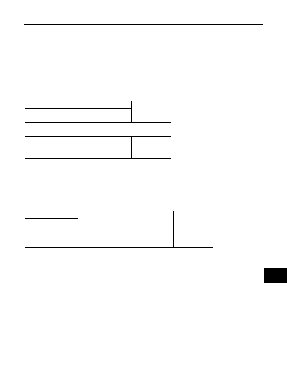
Check continuity between multifunction switch harness connector and AV control unit harness connector.

4.

Check continuity between multifunction switch harness connector and ground.

Is the inspection result normal?

YES

>> GO TO 2.

NO

>> Repair harness or connector.

2.

CHECK AV CONTROL UNIT VOLTAGE 

1.

Connect multifunction switch connector and AV control unit connector.

2.

Turn ignition switch ON.

3.

Check voltage between AV control unit harness connector and ground.

Is the inspection result normal?

YES

>> Replace preset switch.

NO

>> Replace AV control unit.

Multifunction switch

AV control unit

Continuity

Connector

Terminal

Connector

Terminal

M72

14

M202

29

Existed

Multifunction switch

Ground

Continuity

Connector

Terminal

M72

14

Not existed

(+)

(

)

Condition

Voltage

(Approx.)

AV control unit

Connector

Terminal

M202

29

Ground

Pressing the eject switch

0 V

Except for above

5.0 V

AV-148

< DTC/CIRCUIT DIAGNOSIS >

[BOSE AUDIO WITH NAVIGATION]

MICROPHONE SIGNAL CIRCUIT

MICROPHONE SIGNAL CIRCUIT

Description

INFOID:0000000009163413

Supply power from AV control unit to microphone. The microphone transmits the voice signal to the AV control
unit.

Diagnosis Procedure

INFOID:0000000009163414

1.

CHECK CONTINUITY BETWEEN AV CONTROL UNIT AND MICROPHONE CIRCUIT

1.

Turn ignition switch OFF.

2.

Disconnect AV control unit connector and microphone connector.

3.

Check continuity between AV control unit harness connector and microphone harness connector.

4.

Check continuity between AV control unit harness connector and ground.

Is the inspection result normal?

YES

>> GO TO 2.

NO

>> Repair harness or connector.

2.

CHECK VOLTAGE MICROPHONE VCC 

1.

Connect AV control unit connector.

2.

Turn ignition switch ON.

3.

Check voltage between AV control unit harness connector.

Is the inspection result normal?

YES

>> GO TO 3.

NO

>> Replace AV control unit.

3.

CHECK MICROPHONE SIGNAL 

1.

Connect microphone connector.

2.

Check signal between AV control unit harness connector.

AV control unit

Microphone

Continuity

Connector

Terminals

Connector

Terminals

M203

71

R5

2

Existed

72

4

87

1

AV control unit

Ground

Continuity

Connector

Terminals

M203

72

Not existed

87

(+)

(

)

Voltage

(Approx.)

AV control unit

AV control unit

Connector

Terminal

Connector

Terminal

M203

72

M203

71

5.0 V

AV

MICROPHONE SIGNAL CIRCUIT

AV-149

< DTC/CIRCUIT DIAGNOSIS >

[BOSE AUDIO WITH NAVIGATION]

C

D

E

F

G

H

I

J

K

L

M

B

A

O

P

Is the inspection result normal?

YES

>> Replace AV control unit.

NO

>> Replace microphone.

(+)

(

)

Condition

Reference value

AV control unit

AV control unit

Connector

Terminal

Connector

Terminal

M203

87

M203

71

Give a voice.

PKIB5037J

AV-150

< DTC/CIRCUIT DIAGNOSIS >

[BOSE AUDIO WITH NAVIGATION]

CAMERA IMAGE SIGNAL CIRCUIT

CAMERA IMAGE SIGNAL CIRCUIT

Description

INFOID:0000000009163415

• The AV control unit supplies power to the rear view camera when receiving a reverse signal.
• The rear view camera transmits camera images to the display unit when power is supplied from the AV con-

trol unit.

Diagnosis Procedure

INFOID:0000000009163416

1.

CHECK CONTINUITY CAMERA POWER SUPPLY CIRCUIT

1.

Turn ignition switch OFF.

2.

Disconnect AV control unit connector and rear view camera connector.

3.

Check continuity between AV control unit harness connector and rear view camera harness connector.

4.

Check continuity between AV control unit harness connector and ground.

Is inspection result normal?

YES

>> GO TO 2.

NO

>> Repair harness or connector.

2.

CHECK VOLTAGE CAMERA POWER SUPPLY

1.

Connect AV control unit connector and rear view camera connector.

2.

Turn ignition switch ON.

3.

Shift the selector lever to “R”.

4.

Check voltage between AV control unit harness connector and ground.

Is inspection result normal?

YES

>> GO TO 3.

NO

>> Replace AV control unit. Refer to 

AV-168, "Removal and Installation"

.

3.

CHECK CONTINUITY CAMERA IMAGE SIGNAL CIRCUIT

1.

Turn ignition switch OFF.

2.

Disconnect display unit connector and rear view camera connector.

3.

Check continuity between display unit harness connector and rear view camera harness connector.

4.

Check continuity between display unit harness connector and ground.

AV control unit

Rear view camera

Continuity

Connector

Terminal

Connector

Terminal

M202

22

B156

1

Existed

AV control unit

Ground

Continuity

Connector

Terminal

M202

22

Not existed

(+)

(

)

Condition

Voltage

(Approx.)

AV control unit

Connector

Terminal

M202

22

Ground

Shift position is “R”.

6.0 V

Display unit

Rear view camera

Continuity

Connector

Terminal

Connector

Terminal

M93

8

B156

3

Existed


содержание   ..  36  37  38  39   ..