Nissan GT-R. Manual - part 31


  Главная      Nissan     Nissan GT-R (2007-2014 year) - Service Manual


поиск по сайту            


содержание   ..  29  30  31  32   ..


Nissan GT-R. Manual - part 31


AV

DIAGNOSIS SYSTEM (AV CONTROL UNIT)

AV-119

< SYSTEM DESCRIPTION >

[BOSE AUDIO WITH NAVIGATION]

C

D

E

F

G

H

I

J

K

L

M

B

A

O

P

• If there is a malfunction with the GPS antenna circuit board in the AV control unit, the correct date and time

of occurrence may not be able to be displayed.

• Place of the error occurrence is represented by the position of the current location mark at the time an error

occurred. If current location mark has deviated from the correct position, then the place of the error occur-
rence cannot be located correctly.

• The frequency of occurrence is displayed in a count up manner. The actual count up method differs depend-

ing on the error item. 

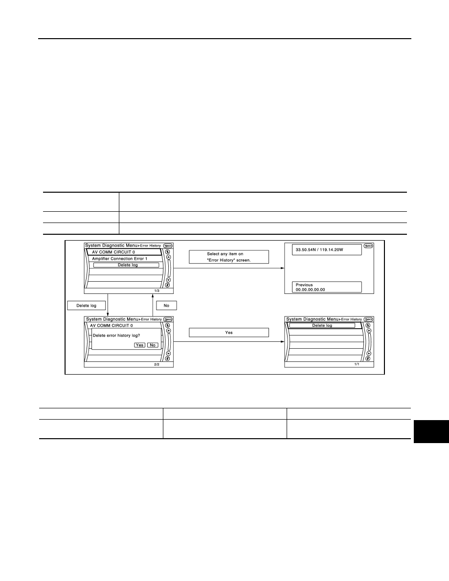
Count up method A
• The counter resets to 0 if an error occurs when IGN switch is turned ON. The counter increases by 1 if the

condition is normal at a next IGN ON cycle. 

• The counter upper limit is 39. Any counts exceeding 39 are ignored.“ The counter can be reset (no error

record display) with the “Delete log” switch or CONSULT.

Count up method B
• The counter increases by 1 if an error occurs when IGN switch is ON. The counter will not decrease even if

the condition is normal at the next IGN ON cycle. 

• The counter upper limit is 50. Any counts exceeding 50 are ignored. “ The counter can be reset (no error

record display) with the “Delete log” switch or CONSULT.

Error item
Some error items may be displayed simultaneously according to the cause. If some error items are displayed
simultaneously, the detection of the cause can be performed by the combination of display items

Display type of occur-

rence frequency

Error history display item

Count up method A

CAN communication line, control unit (CAN), AV communication line, control unit (AV)

Count up method B

Other than the above

JPNIA1788GB

Error item

Description

Possible malfunction factor/Action to take

CAN COMM CIRCUIT

CAN communication malfunction is detect-
ed.

This work is recommended to be performed 
by NHPC.

AV-120

< SYSTEM DESCRIPTION >

[BOSE AUDIO WITH NAVIGATION]

DIAGNOSIS SYSTEM (AV CONTROL UNIT)

CONTROL UNIT (CAN)

CAN initial diagnosis malfunction is detect-
ed.

Replace the AV control unit if the malfunc-
tion occurs constantly.

CONTROL UNIT (AV)

AV communication circuit initial diagnosis 
malfunction is detected.

FLASH-ROM Error Of Control Unit

AV control unit malfunction is detected.

Connection Of Gyro

Connection of G Sensor

CAN Controller Memory Error

Bluetooth Module Connection Error

Sub CPU Connection Error

iPod authentification chip error

Audio connection error

DSP Connection Error

AV control unit malfunction is detected.

• If a disc can be played, then there is a 

possibility of the detection of a temporary 
malfunction.

• Replace the AV control unit if the mal-

function occurs constantly.

DSP Communication Error

HDD Connection Error

AV control unit malfunction is detected.

Replace the AV control unit if the malfunc-
tion occurs constantly.

HDD Read Error

HDD Write Error

HDD Communication Error

HDD Access Error

GPS Communication Error

GPS malfunction is detected.

An intermittent error caused by strong radio 
interference may be detected unless any 
symptom (GPS reception error, etc.) oc-
curs.
Replace the AV control unit if the malfunc-
tion occurs constantly.

GPS ROM Error

GPS RAM Error

GPS RTC Error

Unfinished configuration

The writing of configuration data is incom-
plete.

Write configuration data with CONSULT.

USB Controller Communication Error

USB connection malfunction is detected.

Check that the connection to the USB con-
nector is normal.

DVD Mechanism Communication Error

AV control unit malfunction is detected.

• If DVD can be played, then there is a 

possibility of the detection of a temporary 
malfunction.

• Replace the AV control unit if the mal-

function occurs constantly.

Front Display Connection Error

• Display unit power supply and ground 

circuits malfunction is detected.

• Malfunction is detected in communica-

tion circuits between AV control unit and 
display unit.

• Display unit power supply and ground 

circuits.

• Communication circuits between AV con-

trol unit and display unit.

GPS Antenna Error

GPS antenna connection malfunction is de-
tected.

Check the connection of the GPS antenna 
connector.

XM Antenna Connection Error

Satellite radio antenna connection malfunc-
tion is detected.

• Satellite radio antenna feeder.
• Satellite radio antenna.

USB electric current Error

Detection of over current in USB connector.

Check USB harness between the AV con-
trol unit and USB connector. 

AM/FM antenna amplifier short to ground

Radio antenna amp. ON signal circuit mal-
function is detected.

Radio antenna amp. ON signal circuit  be-
tween AV control unit and antenna amp.

AM/FM antenna amplifier open

Error item

Description

Possible malfunction factor/Action to take

AV

DIAGNOSIS SYSTEM (AV CONTROL UNIT)

AV-121

< SYSTEM DESCRIPTION >

[BOSE AUDIO WITH NAVIGATION]

C

D

E

F

G

H

I

J

K

L

M

B

A

O

P

Vehicle CAN Diagnosis

• CAN communication status and error counter is displayed.
• The error counter displays “OK” if any malfunction was not

detected in the past and displays “0” if a malfunction is detected. It
increases by 1 if the condition is normal at the next ignition switch
ON cycle. The upper limit of the counter is 39.

• The error counter is erased if “Reset” is pressed.

NOTE:
“???” indicates UNKWN

AV COMM Diagnosis

• Displays the communication status between AV control unit (mas-

ter unit) and each unit.

• The error counter displays “OK” if any malfunction was not

detected in the past and displays “0” if a malfunction is detected. It
increases by 1 if the condition is normal at the next ignition switch
ON cycle. The upper limit of the counter is 39.

• The error counter is erased if “Reset” is pressed.

NOTE:
“???” indicates UNKWN

Hands-Free Phone

Ext_Amp_ON output terminal short to 
ground

BOSE amp. ON signal circuit malfunction is 
detected.

BOSE amp. ON signal circuit  between AV 
control unit and BOSE amp.

Ext_Amp_ON output terminal :open

• AV COMM CIRCUIT
• Switches Connection Error

When either one of the following items are 
detected:
• multifunction switch power supply and 

ground circuits are malfunctioning.

• AV communication circuits between AV 

control unit and multifunction switch are 
malfunctioning.

• Multifunction switch power supply and 

ground circuits.

• AV communication circuits between AV 

control unit and multifunction switch.

Error item

Description

Possible malfunction factor/Action to take

Items

Display (Current)

Malfunction counter

(Past)

Tx(HVAC)

OK / ???

OK / 0 – 39

Rx(ECM)

OK / ???

OK / 0 – 39

Rx(Cluster)

OK / ???

OK / 0 – 39

Rx(HVAC)

OK / ???

OK / 0 – 39

Rx(USM)

OK / ???

OK / 0 – 39

Rx (TPMS)

OK / ???

OK / 0 - 39

Rx (VDC)

OK / ???

OK / 0 - 39

NNNIA0188ZZ

Items

Status

(Current)

Counter

(Past)

C Tx(ITM–PrimarySW)

OK / ???

OK / 0 – 39

C Rx(PrimarySW–ITM)

OK / ???

OK / 0 – 39

NNNIA0189ZZ

AV-122

< SYSTEM DESCRIPTION >

[BOSE AUDIO WITH NAVIGATION]

DIAGNOSIS SYSTEM (AV CONTROL UNIT)

The hands-free phone reception volume adjustment and microphone
and speaker test functions are also available.

Camera Cont.

The four functions of “Correct Draw Line of Rear view Camera”,
“Alter/Confirm Configuration”, “Reset Configuration” and “Camera
Syst Type” are available.

Correct Draw Line of Rear view Camera

• Use this mode to adjust the guide line display position of the rear

view monitor if necessary after removing the rear view monitor
camera.

Alter/Confirm Configuration

• Configuration stored in the AV control unit can be checked and modified.

Configuration list

NNNIA0190ZZ

NNNIA0179ZZ

JSNIA2185ZZ

Setting item

Setting

Setting item

Setting

Predi. Course Lines

With

Wheelbase

2.7800000

Rear Coeff. K

133446.7

Total Length

0.0000000

Rear Coeff. F

0.0016960

Steering Gear Ratio

14.368316

Rear Coeff. P1

0.0000046

Side Coeff. K

0.0000000

Rear Coeff. P2

0.0000056

Side Coeff. F

0.0000000

Rear Coeff. C1

823.00000

Side Coeff. P1

0.0000000

Rear Coeff. C2

480.00000

Side Coeff. P2

0.0000000

Rear Coeff. D1

800.00000

Side Coeff. C1

0.0000000

Rear Coeff. D2

494.00000

Side Coeff. C2

0.0000000

Car Width

1.8950000

Side Coeff. D1

0.0000000

Rear Offset

0.207930

Side Coeff. D2

0.0000000

Rear Height

0.6846400

Side Offset

0.0000000


содержание   ..  29  30  31  32   ..