Nissan Pathfinder (2012 year). Manual - part 571
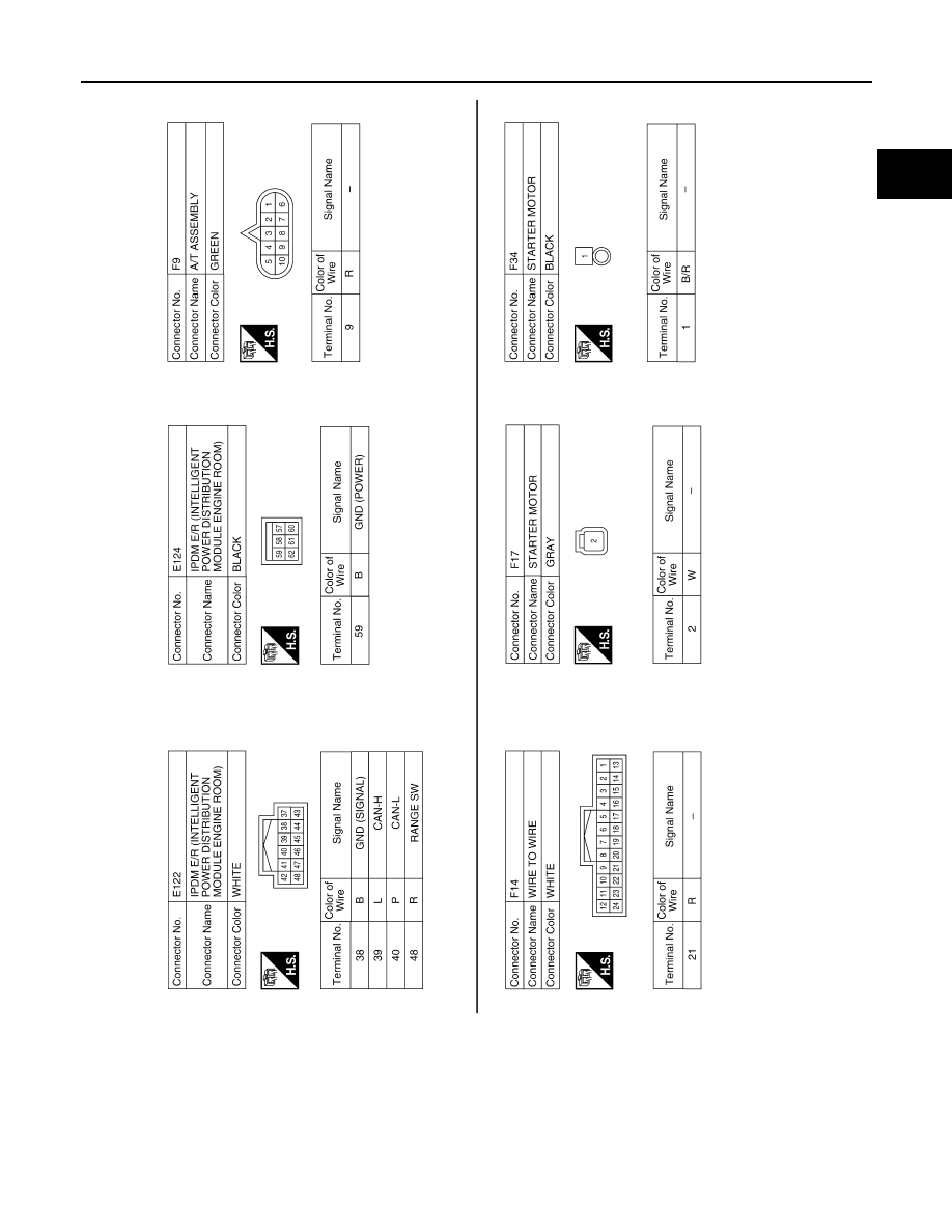
STARTING SYSTEM
STR-25
< WIRING DIAGRAM >
C
D
E
F
G
H
I
J
K
L
M
A
STR
N
P
O
ABBIA0869GB
August 2012
2012 Pathfinder
|
|
|
STARTING SYSTEM STR-25 < WIRING DIAGRAM > C D E F G H I J K L M A STR N P O ABBIA0869GB August 2012 2012 Pathfinder |