Nissan Pathfinder (2012 year). Manual - part 542


  Index      Manuals     Nissan Pathfinder (2012 year) - Service and Repair Manual


Search            copyright infringement  


Content      ..     540      541      542      543     ..


Nissan Pathfinder (2012 year). Manual - part 542


VEHICLE SECURITY SYSTEM

SEC-125

< SYSTEM DESCRIPTION >

[WITHOUT INTELLIGENT KEY SYSTEM]

C

D

E

F

G

H

I

J

L

M

A

B

SEC

N

O

P

Condition of Deactivating The System

When one of the following operations is performed, the armed phase is canceled.

• Unlock the doors with keyfob.

• Use the mechanical key to unlock the driver door using the door key cylinder.

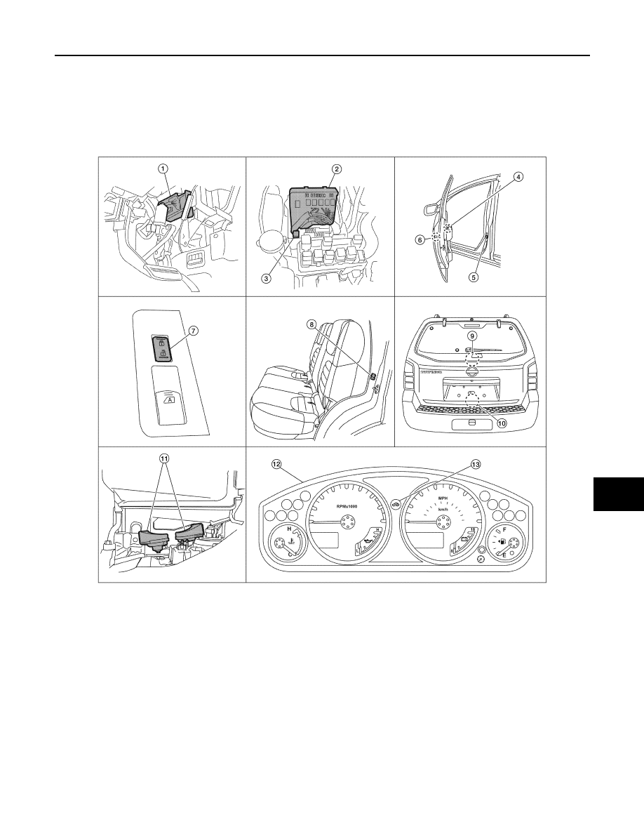
Component Parts Location

INFOID:0000000007355770

1.

BCM M18, M19, M20
(view with instrument panel LH re-
moved)

2.

IPDM E/R E122, E123, E124
(view with cover removed)

3.

Horn relay H-1

4.

Main power window and door lock/
unlock switch D7, D8

5.

Front door switch LH B8
RH B108

6.

Front door lock assembly LH (key cylin-
der switch) D14

7.

Power window and door lock/unlock 
switch RH D105

8.

Rear door switch LH B18
RH B116

9.

Glass hatch ajar switch D503

10. Back door latch (door ajar switch) 

D502
Glass hatch ajar switch D503

11. Horn E3

(behind front combination lamp LH)

12. Combination meter M24

13. Security indicator lamp

ALKIA1718ZZ

August 2012

2012 Pathfinder

2012 Pathfinder

SEC-126

< SYSTEM DESCRIPTION >

[WITHOUT INTELLIGENT KEY SYSTEM]

VEHICLE SECURITY SYSTEM

Component Description

INFOID:0000000007355771

Item

Function

BCM

Verifies the received signal from ignition key, then informs ECM whether to allow engine start.

Door switch

Provides the BCM with the status of each monitored door.

Security indicator

Indicates the status of the security system.

IPDM E/R

Controls the horn and headlamps operation.

Horn

Sounds when the vehicle security system is triggered.

August 2012

2012 Pathfinder

2012 Pathfinder

DIAGNOSIS SYSTEM (BCM)

SEC-127

< SYSTEM DESCRIPTION >

[WITHOUT INTELLIGENT KEY SYSTEM]

C

D

E

F

G

H

I

J

L

M

A

B

SEC

N

O

P

DIAGNOSIS SYSTEM (BCM)

COMMON ITEM
COMMON ITEM : CONSULT Function (BCM - COMMON ITEM)

INFOID:0000000007818232

APPLICATION ITEM

CONSULT performs the following functions via CAN communication with BCM.

SYSTEM APPLICATION

BCM can perform the following functions.

Direct Diagnostic Mode

Description

Ecu Identification

The BCM part number is displayed.

Self Diagnostic Result

The BCM self diagnostic results are displayed.

Data Monitor

The BCM input/output data is displayed in real time.

Active Test

The BCM activates outputs to test components.

Work support

The settings for BCM functions can be changed.

Configuration

• The vehicle specification can be read and saved.
• The vehicle specification can be written when replacing BCM.

CAN Diag Support Mntr

The result of transmit/receive diagnosis of CAN communication is displayed.

System

Sub System

Direct Diagnostic Mode

E

cu

 Id

en

tifi

ca

tio

n

Se

lf Di

ag

no

st

ic Re

su

lt

Da

ta

 Mo

ni

tor

A

cti

ve

 T

est

W

o

rk support

Co

nf

igu

rat

ion

CA

N Diag

 Su

pp

ort Mn

tr

Door lock

DOOR LOCK

×

×

×

Rear window defogger

REAR DEFOGGER

×

×

Warning chime

BUZZER

×

×

Interior room lamp timer

INT LAMP

×

×

×

Remote keyless entry system

MULTI REMOTE ENT

×

×

×

Exterior lamp

HEAD LAMP

×

×

×

Wiper and washer

WIPER

×

×

×

Turn signal and hazard warning lamps FLASHER

×

×

Air conditioner

AIR CONDITIONER

×

Intelligent Key system

INTELLIGENT KEY

×

Combination switch

COMB SW

×

BCM

BCM

×

×

×

×

×

Immobilizer

IMMU

×

×

×

Interior room lamp battery saver

BATTERY SAVER

×

×

×

Back door open

TRUNK

×

×

Vehicle security system

THEFT ALM

×

×

×

RAP system

RETAINED PWR

×

×

×

Signal buffer system

SIGNAL BUFFER

×

×

TPMS

AIR PRESSURE MONITOR

×

×

×

×

Panic alarm system

PANIC ALARM

×

August 2012

2012 Pathfinder

2012 Pathfinder

SEC-128

< SYSTEM DESCRIPTION >

[WITHOUT INTELLIGENT KEY SYSTEM]

DIAGNOSIS SYSTEM (BCM)

IMMU
IMMU : CONSULT Function (BCM - IMMU)

INFOID:0000000007818233

SELF DIAGNOSTIC RESULT

Refer to 

BCS-44, "DTC Index"

.

DATA MONITOR

ACTIVE TEST

THEFT ALM
THEFT ALM : CONSULT Function (BCM - THEFT ALM)

INFOID:0000000007818234

DATA MONITOR

* : with Intelligent Key
** : without Intelligent Key

ACTIVE TEST

WORK SUPPORT

Monitor Item [Unit]

Description

IGN ON SW [On/Off]

Indicates condition of ignition switch ON position.

Test Item

Description

THEFT IND

This test is able to check security indicator operation [Off/On]. 

Monitor Item [Unit]

Description

IGN ON SW [On/Off]

Indicates condition of ignition switch ON position.

ACC ON SW [On/Off]

Indicates condition of ignition switch ACC position.

I-KEY LOCK* [On/Off]

Indicates condition of lock signal from Intelligent Key.

I-KEY UNLOCK* [On/Off]

Indicates condition of unlock signal from Intelligent Key.

KEYLESS LOCK** [On/Off]

Indicates condition of lock signal from keyfob.

KEYLESS UNLOCK** [On/Off]

Indicates condition of unlock signal from keyfob.

DOOR SW-DR [On/Off]

Indicates condition of front door switch LH.

DOOR SW-AS [On/Off]

Indicates condition of front door switch RH.

DOOR SW-RR [On/Off]

Indicates condition of rear door switch RH.

DOOR SW-RL [On/Off]

Indicates condition of rear door switch LH.

BACK DOOR SW [On/Off]

Indicates condition of back door switch.

KEY CYL LK-SW [On/Off]

Indicates condition of lock signal from door key cylinder switch.

KEY CYL UN-SW [On/Off]

Indicates condition of unlock signal from door key cylinder switch.

CDL LOCK SW [On/Off]

Indicates condition of lock signal from door lock and unlock switch.

CDL UNLOCK SW [On/Off]

Indicates condition of unlock signal from door lock and unlock switch.

Test Item

Description

THEFT IND

This test is able to check security indicator lamp operation [Off/On].

VEHICLE SECURITY HORN

This test is able to check vehicle security horn operation [On].

HEADLAMP(HI)

This test is able to check vehicle security lamp operation [On].

August 2012

2012 Pathfinder

2012 Pathfinder

DIAGNOSIS SYSTEM (BCM)

SEC-129

< SYSTEM DESCRIPTION >

[WITHOUT INTELLIGENT KEY SYSTEM]

C

D

E

F

G

H

I

J

L

M

A

B

SEC

N

O

P

*: Initial setting

Support Item

Setting

Description

SECURITY ALARM SET

Off

Security alarm OFF.

On*

Security alarm ON.

THEFT ALM TRG

Off/On

The switch which triggered vehicle security alarm is recorded.

August 2012

2012 Pathfinder

2012 Pathfinder

SEC-130

< DTC/CIRCUIT DIAGNOSIS >

[WITHOUT INTELLIGENT KEY SYSTEM]

U1000 CAN COMM CIRCUIT

DTC/CIRCUIT DIAGNOSIS

U1000 CAN COMM CIRCUIT

Description

INFOID:0000000007355775

CAN (Controller Area Network) is a serial communication line for real time applications. It is an on-vehicle mul-

tiplex communication line with high data communication speed and excellent error detection ability. Modern

vehicle is equipped with many electronic control unit, and each control unit shares information and links with

other control units during operation (not independent). In CAN communication, control units are connected

with 2 communication lines (CAN-H line, CAN-L line) allowing a high rate of information transmission with less

wiring. Each control unit transmits/receives data but selectively reads required data only.

CAN Communication Signal Chart, refer to 

LAN-53, "CAN Communication Signal Chart"

.

DTC Logic

INFOID:0000000007355776

DTC DETECTION LOGIC

Diagnosis Procedure

INFOID:0000000007355777

1.

PERFORM SELF DIAGNOSTIC

1. Turn ignition switch ON and wait for 2 seconds or more.

2. Check “Self Diagnostic Result”.
Is “CAN COMM CIRCUIT” displayed?

YES

>> Refer to 

LAN-5, "CAN Communication Control Circuit"

.

NO

>> Refer to 

GI-37, "Intermittent Incident"

.

DTC

CONSULT display de-

scription

DTC Detection Condition

Possible cause

U1000

CAN COMM CIRCUIT

When BCM cannot communicate CAN com-
munication signal continuously for 2 sec-
onds or more.

In CAN communication system, any item (or items) 
of the following listed below is malfunctioning.
• Receiving (TCM)
• Receiving (IPDM E/R)
• Receiving (ECM)
• Receiving (METER/M&A)
• Receiving (MULTI AV)

August 2012

2012 Pathfinder

2012 Pathfinder

U1010 CONTROL UNIT (CAN)

SEC-131

< DTC/CIRCUIT DIAGNOSIS >

[WITHOUT INTELLIGENT KEY SYSTEM]

C

D

E

F

G

H

I

J

L

M

A

B

SEC

N

O

P

U1010 CONTROL UNIT (CAN)

Description

INFOID:0000000007355778

CAN (Controller Area Network) is a serial communication line for real time applications. It is an on-vehicle mul-

tiplex communication line with high data communication speed and excellent error detection ability. Modern

vehicle is equipped with many electronic control unit, and each control unit shares information and links with

other control units during operation (not independent). In CAN communication, control units are connected

with 2 communication lines (CAN-H line, CAN-L line) allowing a high rate of information transmission with less

wiring. Each control unit transmits/receives data but selectively reads required data only.

CAN Communication Signal Chart, refer to 

LAN-53, "CAN Communication Signal Chart"

.

DTC Logic

INFOID:0000000007355779

DTC DETECTION LOGIC

Diagnosis Procedure

INFOID:0000000007355780

1.

REPLACE BCM

When DTC [U1010] is detected, replace BCM.

>> Replace BCM. Refer to 

BCS-53,"Removal and Installation’

.

Special Repair Requirement

INFOID:0000000007355781

1.

REQUIRED WORK WHEN REPLACING BCM

Initialize BCM. Refer to CONSULT Immobilizer mode and follow the on-screen instructions.

>> Inspection End.

DTC

CONSULT display de-

scription

DTC Detection Condition

Possible cause

U1010

CONTROL UNIT (CAN)

When detecting error during the initial diagnosis of CAN control-
ler of BCM.

BCM

2012 Pathfinder

SEC-132

< DTC/CIRCUIT DIAGNOSIS >

[WITHOUT INTELLIGENT KEY SYSTEM]

B2190, P1614 NATS ANTENNA AMP.

B2190, P1614 NATS ANTENNA AMP.

Description

INFOID:0000000007355782

Performs ID verification through BCM and NATS antenna amplifier when ignition key is inserted and ignition

switch turned ON.

Prohibits the start of engine when an unregistered ID of ignition key is used.

DTC Logic

INFOID:0000000007355783

DTC DETECTION LOGIC

DTC CONFIRMATION PROCEDURE

1.

PERFORM DTC CONFIRMATION PROCEDURE

1. Insert ignition key into the key cylinder.

2. Turn ignition switch ON.

3. Check “Self diagnostic result” with CONSULT.
Is DTC detected?

YES

>> Refer to 

SEC-132, "Diagnosis Procedure"

.

NO

>> Inspection End.

Diagnosis Procedure

INFOID:0000000007355784

Regarding Wiring Diagram information, refer to 

SEC-177, "Wiring Diagram - Without Intelligent Key System"

.

1.

CHECK NATS ANTENNA AMP. INSTALLATION

Check NATS antenna amp. installation. Refer to 

SEC-184, "Removal and Installation"

.

Is the inspection result normal?

YES

>> GO TO 2

NO

>> Reinstall NATS antenna amp. correctly.

2.

CHECK NVIS (NATS) IGNITION KEY ID CHIP

Start engine with another registered NATS ignition key.
Does the engine start?

YES

>> • Ignition key ID chip is malfunctioning.

• Replace the ignition key.

• Perform initialization with CONSULT.

For initialization, refer to CONSULT Immobilizer mode and follow the on-screen instructions.

NO

>> GO TO 3

3.

CHECK POWER SUPPLY FOR NATS ANTENNA AMP.

1. Turn ignition switch OFF.

2. Check voltage between NATS antenna amp. connector M21 terminal 1 and ground.

DTC No.

Trouble diagnosis 

name

DTC detecting condition

Possible cause

B2190

NATS ANTENNA 
AMP

• Inactive communication between NATS antenna 

amp. and BCM.

• Ignition key is malfunctioning.

• Harness or connectors

(The NATS antenna amp. circuit is 
open or shorted)

• Ignition  key
• NATS antenna amp.
• BCM

P1614

2012 Pathfinder


Content      ..     540      541      542      543     ..