Nissan Pathfinder (2012 year). Manual - part 530
U1010 CONTROL UNIT (CAN)
SEC-29
< DTC/CIRCUIT DIAGNOSIS >
[WITH INTELLIGENT KEY SYSTEM]
C
D
E
F
G
H
I
J
L
M
A
B
SEC
N
O
P
U1010 CONTROL UNIT (CAN)
Description
INFOID:0000000007355687
CAN (Controller Area Network) is a serial communication line for real time applications. It is an on-vehicle mul-
tiplex communication line with high data communication speed and excellent error detection ability. Modern
vehicle is equipped with many electronic control unit, and each control unit shares information and links with
other control units during operation (not independent). In CAN communication, control units are connected
with 2 communication lines (CAN-H line, CAN-L line) allowing a high rate of information transmission with less
wiring. Each control unit transmits/receives data but selectively reads required data only.
CAN Communication Signal Chart, refer to
LAN-53, "CAN Communication Signal Chart"
DTC Logic
INFOID:0000000007355688
DTC DETECTION LOGIC
Diagnosis Procedure
INFOID:0000000007355689
1.
REPLACE INTELLIGENT KEY UNIT
When DTC [U1010] is detected, replace Intelligent Key unit.
>> Replace Intelligent Key unit. Refer to
SEC-114, "Removal and Installation"
Special Repair Requirement
INFOID:0000000007355690
1.
REQUIRED WORK WHEN REPLACING INTELLIGENT KEY UNIT
Initialize control unit. Refer to CONSULT Immobilizer mode and follow the on-screen instructions.
>> Inspection End.
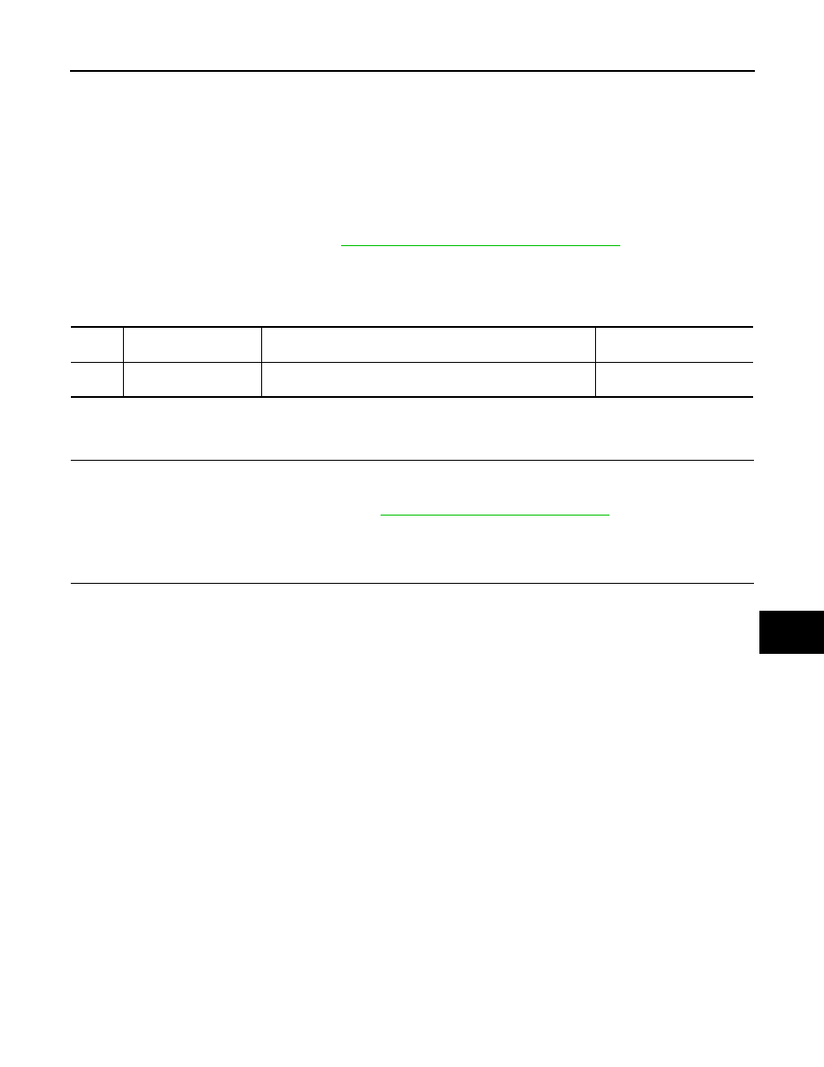
DTC
CONSULT display de-
scription
DTC Detection Condition
Possible cause
U1010
CONTROL UNIT (CAN)
When detecting error during the initial diagnosis of CAN control-
ler of Intelligent Key unit.
Intelligent Key unit
2012 Pathfinder