Nissan Pathfinder (2012 year). Manual - part 471
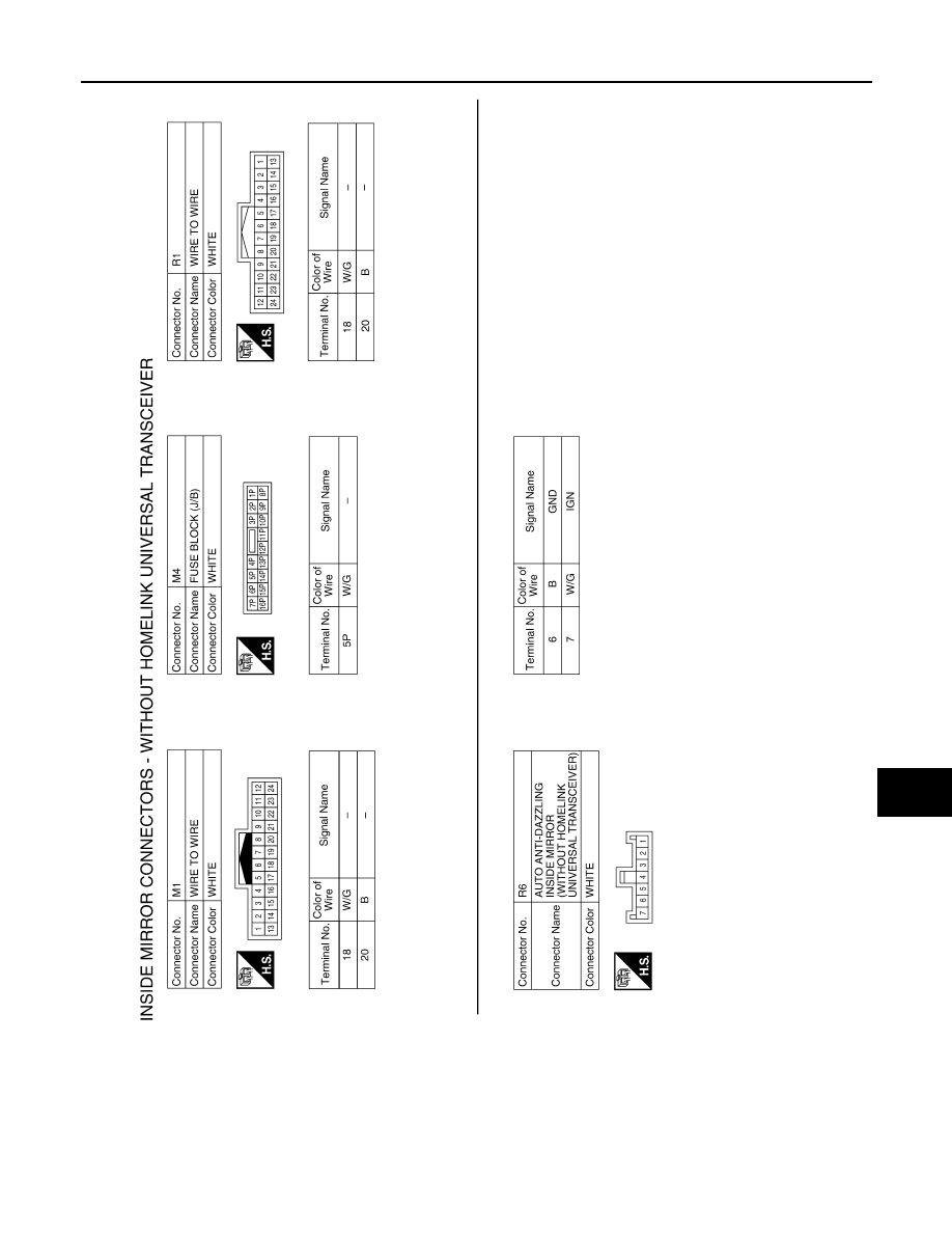
INSIDE MIRROR
MIR-11
< WIRING DIAGRAM >
C
D
E
F
G
H
I
J
K
M
A
B
MIR
N
O
P
ABLIA1697GB
August 2012
2012 Pathfinder
|
|
|
INSIDE MIRROR MIR-11 < WIRING DIAGRAM > C D E F G H I J K M A B MIR N O P ABLIA1697GB August 2012 2012 Pathfinder |