Nissan Pathfinder (2012 year). Manual - part 462


  Index      Manuals     Nissan Pathfinder (2012 year) - Service and Repair Manual


Search            copyright infringement  


Content      ..     460      461      462      463     ..


Nissan Pathfinder (2012 year). Manual - part 462


LU-34

< UNIT DISASSEMBLY AND ASSEMBLY >

[VK56DE]

OIL PUMP

UNIT DISASSEMBLY AND ASSEMBLY

OIL PUMP

Disassembly and Assembly

INFOID:0000000007357897

DISASSEMBLY

1. Remove oil pump cover.
2. Remove inner rotor and outer rotor from oil pump body. 
3. Remove the regulator valve plug, regulator valve spring and regulator valve.

INSPECTION AFTER DISASSEMBLY 

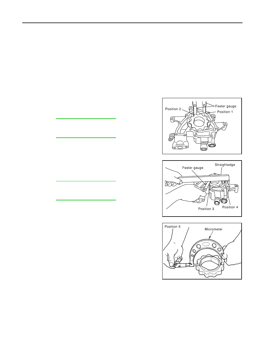
Clearance of Oil Pump Parts

• Measure radial clearance using a suitable tool.

• Measure side clearance using suitable tools.

• Calculate the clearance between inner rotor and oil pump body as

follows.

1. Measure the outer diameter of protruded portion of inner rotor

(position 5) using suitable tool.

Body to outer rotor (position 1)
Refer to 

LU-36, "Standard and Limit"

.

Inner rotor to outer rotor tip (position 2)
Refer to 

LU-36, "Standard and Limit"

.

PBIC0139E

Body to inner rotor (position 3)
Refer to 

LU-36, "Standard and Limit"

.

Body to outer rotor (position 4)
Refer to 

LU-36, "Standard and Limit"

.

PBIC0140E

PBIC0141E

August 2012

2012 Pathfinder

OIL PUMP

LU-35

< UNIT DISASSEMBLY AND ASSEMBLY >

[VK56DE]

C

D

E

F

G

H

I

J

K

L

M

A

LU

N

P

O

2. Measure the inner diameter of oil pump body to brazed portion

(position 6) using suitable tool.

3. Calculate the clearance using the following formula.

• (Clearance) = (Inner diameter of oil pump body) - (Outer diameter of inner rotor)

Regulator Valve Clearance

Check regulator valve to oil pump cover clearance using the following formula.

• (Clearance) = D

1

 (Valve hole diameter) - D

2

 (Outer Diameter of

valve)

CAUTION:

• Coat regulator valve with engine oil.

• Check that it falls smoothly into the regulator valve hole by its

own weight.

ASSEMBLY

Installation is in the reverse order of removal.

NOTE:

• Install oil pump inner rotor with the punch mark facing the oil pump

cover side. 

• Install the oil pump outer rotor with the punch mark facing the oil

pump cover side.

PBIC0142E

Inner rotor to brazed portion of housing 
clearance
Refer to 

LU-36, "Standard and Limit"

.

Regulator valve to oil pump cover
Refer to 

LU-36, "Standard and Limit"

.

PBIC0143E

PBIC0144E

August 2012

2012 Pathfinder

LU-36

< SERVICE DATA AND SPECIFICATIONS (SDS) 

[VK56DE]

SERVICE DATA AND SPECIFICATIONS (SDS)

SERVICE DATA AND SPECIFICATIONS (SDS)

SERVICE DATA AND SPECIFICATIONS (SDS)

Standard and Limit

INFOID:0000000007357898

OIL PRESSURE

Unit: kPa (kg/cm

2, psi)

*: Engine oil temperature at 80

°

C (176

°

F) 

OIL PUMP

Unit: mm (in)

REGULATOR VALVE

Unit: mm (in)

ENGINE OIL CAPACITY (APPROXIMATE)

Unit:   (US qt, Imp qt)

Engine speed

Approximate discharge oil pressure*

Idle speed

More than 98 (1.0, 14)

2,000 rpm

More than 294 (3.0, 43)

6,000 rpm

More than 392 (4.0, 56.8) 

Body to outer rotor (Position 1)

0.114 - 0.200 (0.0045 - 0.0079)

Inner rotor to outer rotor tip (Position 2)

Below 0.180 (0.0071)

Body to inner rotor (Position 3)

0.030 - 0.070 (0.0012 - 0.0028)

Body to outer rotor (Position 4)

0.030 - 0.090 (0.0012 - 0.0035)

Inner rotor to brazed portion of housing 

0.045 - 0.091 (0.0018 - 0.0036)

Regulator valve to oil pump cover 

0.040 - 0.097 (0.0016 - 0.0038)

Drain and refill

With oil filter change

6.5 (6-7/8, 5-3/4)

Without oil filter change

6.2 (6-1/2, 5-1/2)

Dry engine (engine overhaul)

7.6 (8, 6-3/4)         

August 2012

2012 Pathfinder

MA-1

MAINTENANCE

C

D

E

F

G

H

I

J

K

L

M

B

MA

SECTION 

MA

N

O

A

CONTENTS

MAINTENANCE

PRECAUTION ...............................................

4

PRECAUTIONS ...................................................

4

Precaution for Supplemental Restraint System 
(SRS) "AIR BAG" and "SEAT BELT PRE-TEN-
SIONER" .................................................................
..

4

Precaution Necessary for Steering Wheel Rota-
tion After Battery Disconnect ...................................
..

4

PREPARATION ............................................

6

PREPARATION ...................................................

6

Special Service Tool  .................................................

6

Commercial Service Tool  ..........................................

6

PERIODIC MAINTENANCE ..........................

7

GENERAL MAINTENANCE ................................

7

FOR USA AND CANADA ............................................

7

FOR USA AND CANADA : General Maintenance ......

7

FOR MEXICO  ..............................................................

9

FOR MEXICO : General Maintenance  ......................

9

PERIODIC MAINTENANCE  ...............................

11

FOR USA AND CANADA ..........................................

11

FOR USA AND CANADA : Introduction to Periodic 
Maintenance ............................................................

11

FOR USA AND CANADA : Periodic Maintenance 
Schedule 1  ..............................................................

11

FOR USA AND CANADA : Periodic Maintenance 
Schedule 2  ..............................................................

14

FOR MEXICO  ............................................................

15

FOR MEXICO : Periodic Maintenance Schedule ....

15

RECOMMENDED FLUIDS AND LUBRI-
CANTS ................................................................

18

FOR USA AND CANADA ..........................................

18

FOR USA AND CANADA : Fluids and Lubricants ....

18

FOR USA AND CANADA : SAE Viscosity Number 

....

19

FOR USA AND CANADA : Anti-Freeze Coolant 
Mixture Ratio  ...........................................................

19

FOR MEXICO .............................................................

20

FOR MEXICO : Fluids and Lubricants .....................

20

FOR MEXICO : SAE Viscosity Number ...................

20

FOR MEXICO : Engine Coolant Mixture Ratio  ........

21

ENGINE MAINTENANCE (VQ40DE) ................

23

DRIVE BELTS ............................................................

23

DRIVE BELTS : Exploded View  ..............................

23

DRIVE BELTS : Checking Drive Belts .....................

23

ENGINE COOLANT  ...................................................

23

ENGINE COOLANT : System Inspection  ................

23

ENGINE COOLANT : Changing Engine Coolant ....

24

FUEL LINES ...............................................................

27

FUEL LINES : Checking Fuel Line  ..........................

27

FUEL FILTER .............................................................

27

FUEL FILTER : Changing Fuel Filter .......................

27

AIR CLEANER FILTER  .............................................

27

AIR CLEANER FILTER : Exploded View  ................

28

AIR CLEANER FILTER : Removal and Installation 

....

28

ENGINE OIL ...............................................................

28

ENGINE OIL : Inspection .........................................

28

ENGINE OIL : Changing Engine Oil  ........................

28

OIL FILTER  ................................................................

29

OIL FILTER : Removal and Installation ...................

29

SPARK PLUG  ............................................................

30

SPARK PLUG : Exploded View ...............................

31

SPARK PLUG : Removal and Installation  ...............

31

EVAP VAPOR LINES  ................................................

32

August 2012

2012 Pathfinder

MA-2

EVAP VAPOR LINES : Checking EVAP Vapor 
Line ........................................................................
.

32

ENGINE MAINTENANCE (VK56DE) .................

33

DRIVE BELTS  ...........................................................

33

DRIVE BELTS : Exploded View  .............................

33

DRIVE BELTS : Checking Drive Belts  ....................

33

ENGINE COOLANT  ..................................................

33

ENGINE COOLANT : System Inspection  ...............

33

ENGINE COOLANT : Changing Engine Coolant ...

34

FUEL LINES ..............................................................

36

FUEL LINES : Checking Fuel Line  .........................

36

FUEL FILTER ............................................................

36

FUEL FILTER : Changing Fuel Filter ......................

37

AIR CLEANER FILTER .............................................

37

AIR CLEANER FILTER : Exploded View  ...............

37

AIR CLEANER FILTER : Removal and Installation 

...

37

ENGINE OIL  ..............................................................

37

ENGINE OIL : Inspection ........................................

37

ENGINE OIL : Changing Engine Oil  .......................

38

OIL FILTER  ...............................................................

38

OIL FILTER : Removal and Installation  ..................

38

SPARK PLUG  ...........................................................

39

SPARK PLUG : Exploded View ..............................

40

SPARK PLUG : Removal and Installation ..............

40

EVAP VAPOR LINES ................................................

41

EVAP VAPOR LINES : Checking EVAP Vapor 
Line ........................................................................
.

41

CHASSIS AND BODY MAINTENANCE ............

42

IN-CABIN MICROFILTER  .........................................

42

IN-CABIN MICROFILTER : Removal and Installa-
tion .........................................................................
.

42

EXHAUST SYSTEM ..................................................

42

EXHAUST SYSTEM : Checking the Exhaust Sys-
tem .........................................................................
.

43

A/T FLUID  .................................................................

43

A/T FLUID : Checking the A/T Fluid (ATF)  .............

43

A/T FLUID : Changing the A/T Fluid (ATF) .............

45

TRANSFER FLUID ....................................................

46

TRANSFER FLUID : ATX14B  ................................

46

TRANSFER FLUID : Inspection  .............................

46

TRANSFER FLUID : Replacement .........................

46

TRANSFER FLUID : TX15B  ...................................

47

TRANSFER FLUID : Inspection  .............................

47

TRANSFER FLUID : Replacement .........................

47

PROPELLER SHAFT ................................................

48

PROPELLER SHAFT : Checking Propeller Shaft ...

48

DIFFERENTIAL GEAR OIL .......................................

48

DIFFERENTIAL GEAR OIL : Front Final Drive 
R180A .....................................................................

48

DIFFERENTIAL GEAR OIL : Checking Differential 
Gear Oil ...................................................................

48

DIFFERENTIAL GEAR OIL : Changing Differen-
tial Gear Oil  .............................................................

48

DIFFERENTIAL GEAR OIL : Front Final Drive 
M205 .......................................................................

49

DIFFERENTIAL GEAR OIL : Checking Differential 
Gear Oil ...................................................................

49

DIFFERENTIAL GEAR OIL : Changing Differen-
tial Gear Oil  .............................................................

49

DIFFERENTIAL GEAR OIL : Rear Final Drive 
R200 .......................................................................

50

DIFFERENTIAL GEAR OIL : Checking Differential 
Gear Oil ...................................................................

50

DIFFERENTIAL GEAR OIL : Changing Differen-
tial Gear Oil  .............................................................

50

DIFFERENTIAL GEAR OIL : Rear Final Drive 
R230 .......................................................................

51

DIFFERENTIAL GEAR OIL : Checking Differential 
Gear Oil ...................................................................

51

DIFFERENTIAL GEAR OIL : Changing Differen-
tial Gear Oil  .............................................................

51

WHEELS ....................................................................

52

WHEELS : Adjustment ............................................

52

BRAKE FLUID LEVEL AND LEAKS  ........................

54

BRAKE FLUID LEVEL AND LEAKS : Checking 
Brake Fluid Level and Leaks ...................................

54

BRAKE FLUID LEVEL AND LEAKS : Drain and 
Refill ........................................................................

54

BRAKE LINES AND CABLES  ..................................

54

BRAKE LINES AND CABLES : Checking Brake 
Line and Cables  ......................................................

55

DISC BRAKE .............................................................

55

DISC BRAKE : Checking Disc Brake ......................

55

STEERING GEAR AND LINKAGE  ...........................

55

STEERING GEAR AND LINKAGE : Checking 
Steering Gear and Linkage  .....................................

55

POWER STEERING FLUID AND LINES  ..................

56

POWER STEERING FLUID AND LINES : Check-
ing Fluid Level .........................................................

56

POWER STEERING FLUID AND LINES : Check-
ing Fluid Leakage ....................................................

56

AXLE AND SUSPENSION PARTS ...........................

56

AXLE AND SUSPENSION PARTS : Checking 
Axle and Suspension Parts .....................................

56

LOCKS, HINGES AND HOOD LATCH .....................

57

LOCKS, HINGES AND HOOD LATCH : Lubricat-
ing Locks, Hinges and Hood Latches  .....................

58

SEAT BELT, BUCKLES, RETRACTORS, AN-
CHORS AND ADJUSTERS  ......................................

58

August 2012

2012 Pathfinder

MA-4

< PRECAUTION >

PRECAUTIONS

PRECAUTION

PRECAUTIONS

Precaution for Supplemental Restraint System (SRS) "AIR BAG" and "SEAT BELT 
PRE-TENSIONER"

INFOID:0000000007347339

The Supplemental Restraint System such as “AIR BAG” and “SEAT BELT PRE-TENSIONER”, used along

with a front seat belt, helps to reduce the risk or severity of injury to the driver and front passenger for certain

types of collision. This system includes seat belt switch inputs and dual stage front air bag modules. The SRS

system uses the seat belt switches to determine the front air bag deployment, and may only deploy one front

air bag, depending on the severity of a collision and whether the front occupants are belted or unbelted.

Information necessary to service the system safely is included in the SR and SB section of this Service Man-

ual.

WARNING:

• To avoid rendering the SRS inoperative, which could increase the risk of personal injury or death in

the event of a collision which would result in air bag inflation, all maintenance must be performed by

an authorized NISSAN/INFINITI dealer.

• Improper maintenance, including incorrect removal and installation of the SRS, can lead to personal

injury caused by unintentional activation of the system. For removal of Spiral Cable and Air Bag

Module, see the SR section.

• Do not use electrical test equipment on any circuit related to the SRS unless instructed to in this

Service Manual. SRS wiring harnesses can be identified by yellow and/or orange harnesses or har-

ness connectors.

PRECAUTIONS WHEN USING POWER TOOLS (AIR OR ELECTRIC) AND HAMMERS

WARNING:

• When working near the Airbag Diagnosis Sensor Unit or other Airbag System sensors with the Igni-

tion ON or engine running, DO NOT use air or electric power tools or strike near the sensor(s) with a

hammer. Heavy vibration could activate the sensor(s) and deploy the air bag(s), possibly causing

serious injury.

• When using air or electric power tools or hammers, always switch the Ignition OFF, disconnect the

battery, and wait at least 3 minutes before performing any service.

Precaution Necessary for Steering Wheel Rotation After Battery Disconnect

INFOID:0000000007347340

NOTE:

• This Procedure is applied only to models with Intelligent Key system and NATS (NISSAN ANTI-THEFT SYS-

TEM).

• Remove and install all control units after disconnecting both battery cables with the ignition knob in the

LOCK

 position.

• Always use CONSULT to perform self-diagnosis as a part of each function inspection after finishing work. If

DTC is detected, perform trouble diagnosis according to self-diagnostic results.

For models equipped with the Intelligent Key system and NATS, an electrically controlled steering lock mech-

anism is adopted on the key cylinder.

For this reason, if the battery is disconnected or if the battery is discharged, the steering wheel will lock and

steering wheel rotation will become impossible.

If steering wheel rotation is required when battery power is interrupted, follow the procedure below before

starting the repair operation.

OPERATION PROCEDURE

1. Connect both battery cables.

NOTE:

Supply power using jumper cables if battery is discharged.

2. Use the Intelligent Key or mechanical key to turn the ignition switch to the 

ACC

 position. At this time, the

steering lock will be released.

3. Disconnect both battery cables. The steering lock will remain released and the steering wheel can be

rotated.

4. Perform the necessary repair operation.

August 2012

2012 Pathfinder

PRECAUTIONS

MA-5

< PRECAUTION >

C

D

E

F

G

H

I

J

K

L

M

B

MA

N

O

A

5. When the repair work is completed, return the ignition switch to the 

LOCK

 position before connecting

the battery cables. (At this time, the steering lock mechanism will engage.)

6. Perform a self-diagnosis check of all control units using CONSULT. 

August 2012

2012 Pathfinder


Content      ..     460      461      462      463     ..