Nissan Pathfinder (2012 year). Manual - part 434
HAC-194
< PRECAUTION >
[MANUAL AIR CONDITIONER]
PRECAUTIONS
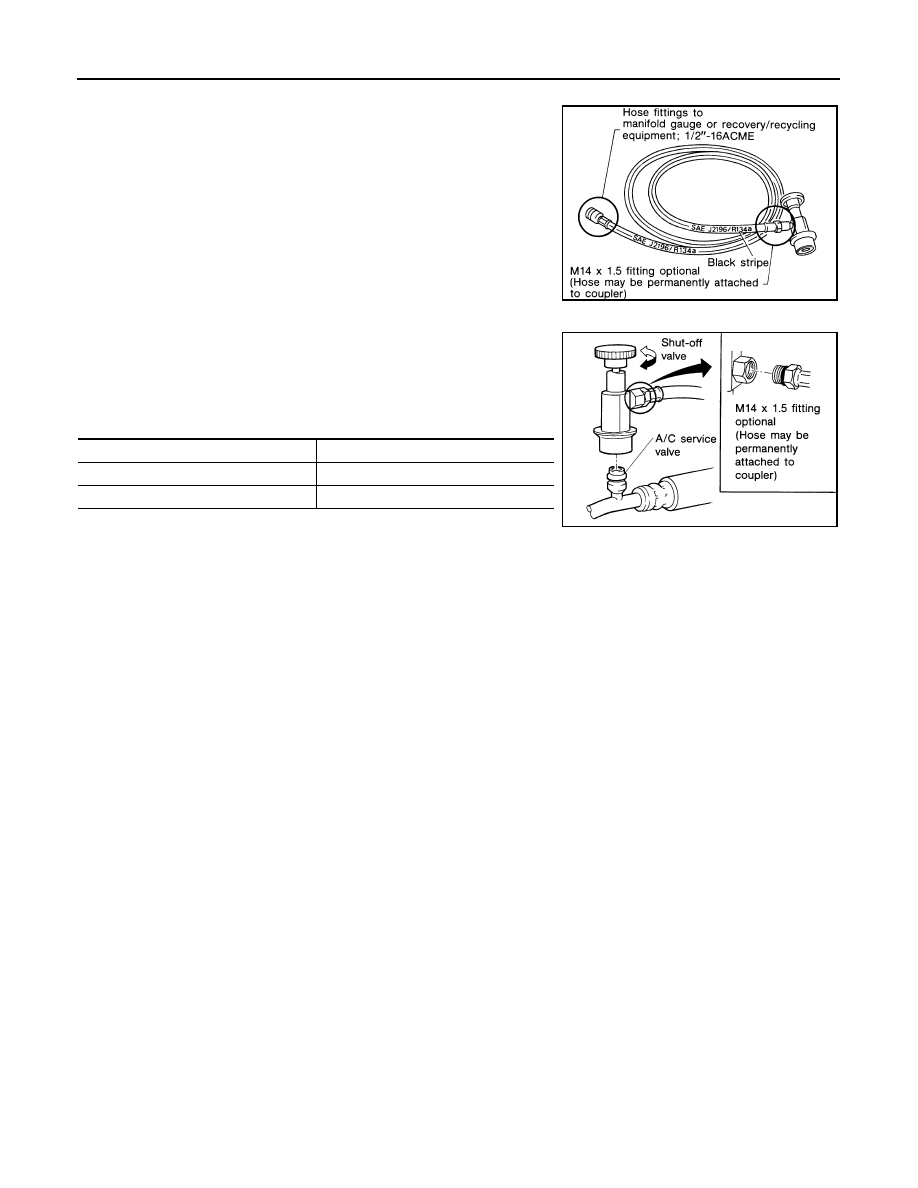
SERVICE HOSES
Be certain that the service hoses display the markings described
(colored hose with black stripe). All hoses must include positive shut-
off devices (either manual or automatic) near the end of the hoses
opposite the manifold gauge.
SERVICE COUPLERS
Never attempt to connect HFC-134a (R-134a) service couplers to a
CFC-12 (R-12) A/C system. The HFC-134a (R-134a) couplers will
not properly connect to the CFC-12 (R-12) system. However, if an
improper connection is attempted, discharging and contamination
may occur.
RHA272D
Shut-off valve rotation
A/C service valve
Clockwise
Open
Counterclockwise
Close
RHA273D
August 2012
2012 Pathfinder