Nissan Pathfinder (2012 year). Manual - part 430
HAC-162
< DTC/CIRCUIT DIAGNOSIS >
[MANUAL AIR CONDITIONER]
MAGNET CLUTCH
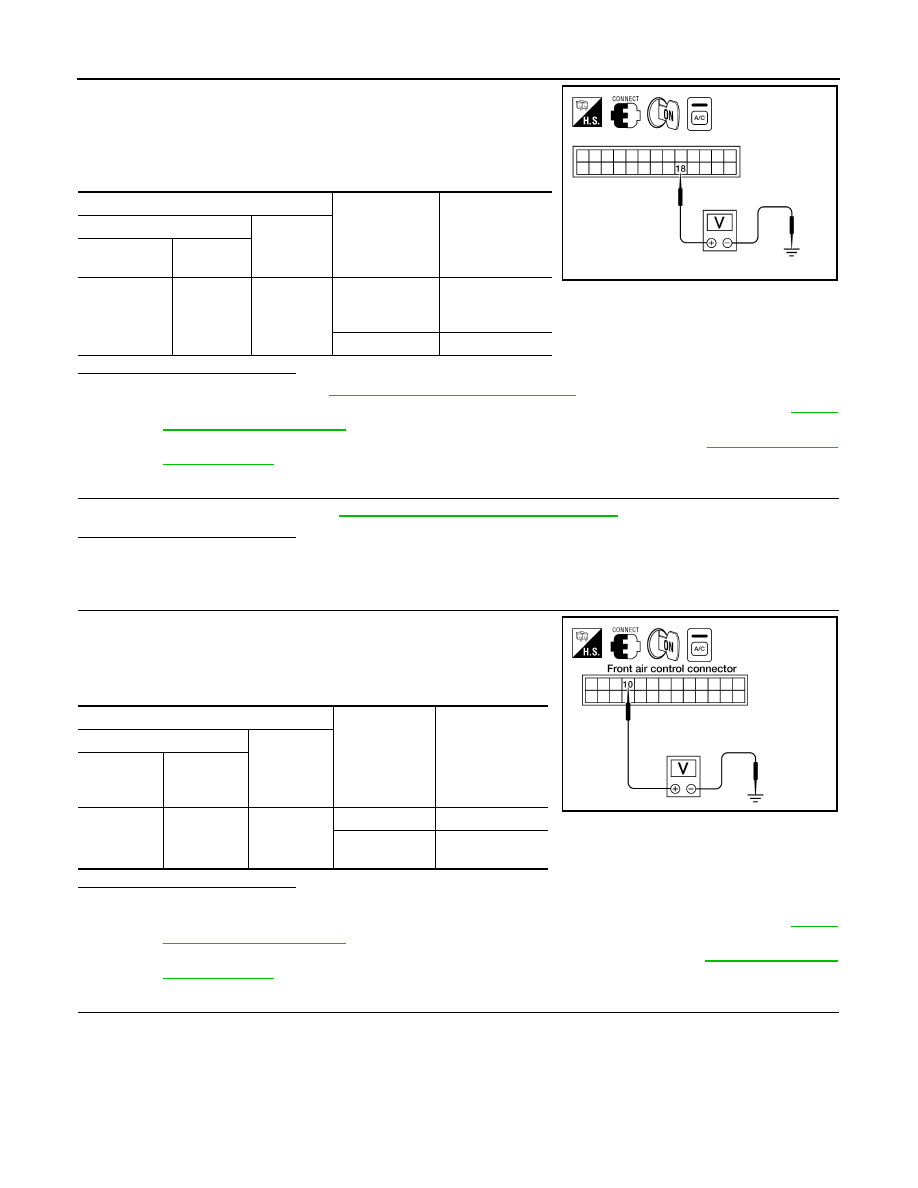
1. Reconnect BCM connector and front air control connector.
2. Turn ignition switch ON.
3. Turn A/C switch ON.
4. Check voltage between front air control harness connector M52
terminal 18 and ground.
Is the inspection result normal?
YES
>> Replace BCM. Refer to
BCS-53, "Removal and Installation"
NO-1 >> If the voltage is approx. 5V when blower motor is ON, replace front air control. Refer to
.
NO-2 >> If the voltage is approx. 0V when blower motor is OFF, replace BCM. Refer to
.
7.
CHECK CAN COMMUNICATION
Check CAN communication. Refer to
LAN-14, "Trouble Diagnosis Flow Chart"
.
Is the inspection result normal?
YES
>> Inspection End.
NO
>> Repair or replace malfunctioning part(s).
8.
CHECK VOLTAGE FOR FRONT AIR CONTROL (A/C COMPRESSOR ON SIGNAL)
1. Reconnect BCM connector and front air control connector.
2. Turn ignition switch ON.
3. Check voltage between front air control harness connector M52
terminal 10 and ground.
Is the inspection result normal?
YES
>> GO TO 9.
NO-1 >> If the voltage is approx. 5V when A/C switch is ON, replace front air control. Refer to
.
NO-2 >> If the voltage is approx. 0V when A/C switch is OFF, replace BCM. Refer to
.
9.
CHECK CIRCUIT CONTINUITY BETWEEN BCM AND FRONT AIR CONTROL
1. Disconnect BCM connector and front air control connector.
2. Check continuity between BCM harness connector M18 terminal 27 and front air control harness connec-
tor M52 terminal 10.
3. Check continuity between BCM harness connector M18 terminal 27 and ground.
Terminals
Condition
Voltage
(Approx.)
(+)
(-)
Front air con-
trol connector
Terminal
No.
M52
18
Ground
A/C switch: ON
Blower motor
operates
0V
A/C switch: OFF
Battery voltage
WJIA1628E
Terminals
Condition
Voltage
(Approx.)
(+)
(-)
Front air
control con-
nector
Terminal No.
M52
10
Ground
A/C switch: ON
Approx. 0V
A/C switch:
OFF
Approx. 5V
WJIA1137E
27 - 10
: Continuity should exist.
August 2012
2012 Pathfinder