Nissan Pathfinder (2012 year). Manual - part 394
HOW TO USE THIS MANUAL
GI-5
< HOW TO USE THIS MANUAL >
C
D
E
F
G
H
I
J
K
L
M
B
GI
N
O
P
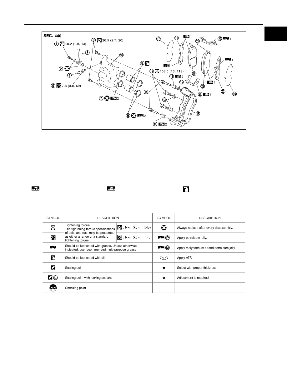
SYMBOLS
1.
Union bolt
2.
Copper washer
3.
Brake hose
4.
Cap
5.
Bleed valve
6.
Sliding pin bolt
7.
Piston seal
8.
Piston
9.
Piston boot
10. Cylinder body
11. Sliding pin
12. Torque member mounting bolt
13. Washer
14. Sliding pin boot
15. Bushing
16. Torque member
17. Inner shim cover
18. Inner shim
19. Inner pad
20. Pad retainer
21. Pad wear sensor
22. Outer pad
23. Outer shim
24. Outer shim cover
1: PBC (Poly Butyl Cuprysil) grease
or silicone-based grease
2: Rubber grease
: Brake fluid
Refer to GI section for additional symbol definitions.
SFIA2959E
SAIA0749E
August 2012
2012 Pathfinder