Nissan Pathfinder (2012 year). Manual - part 383
EXT-26
< REMOVAL AND INSTALLATION >
MUDGUARD
MUDGUARD
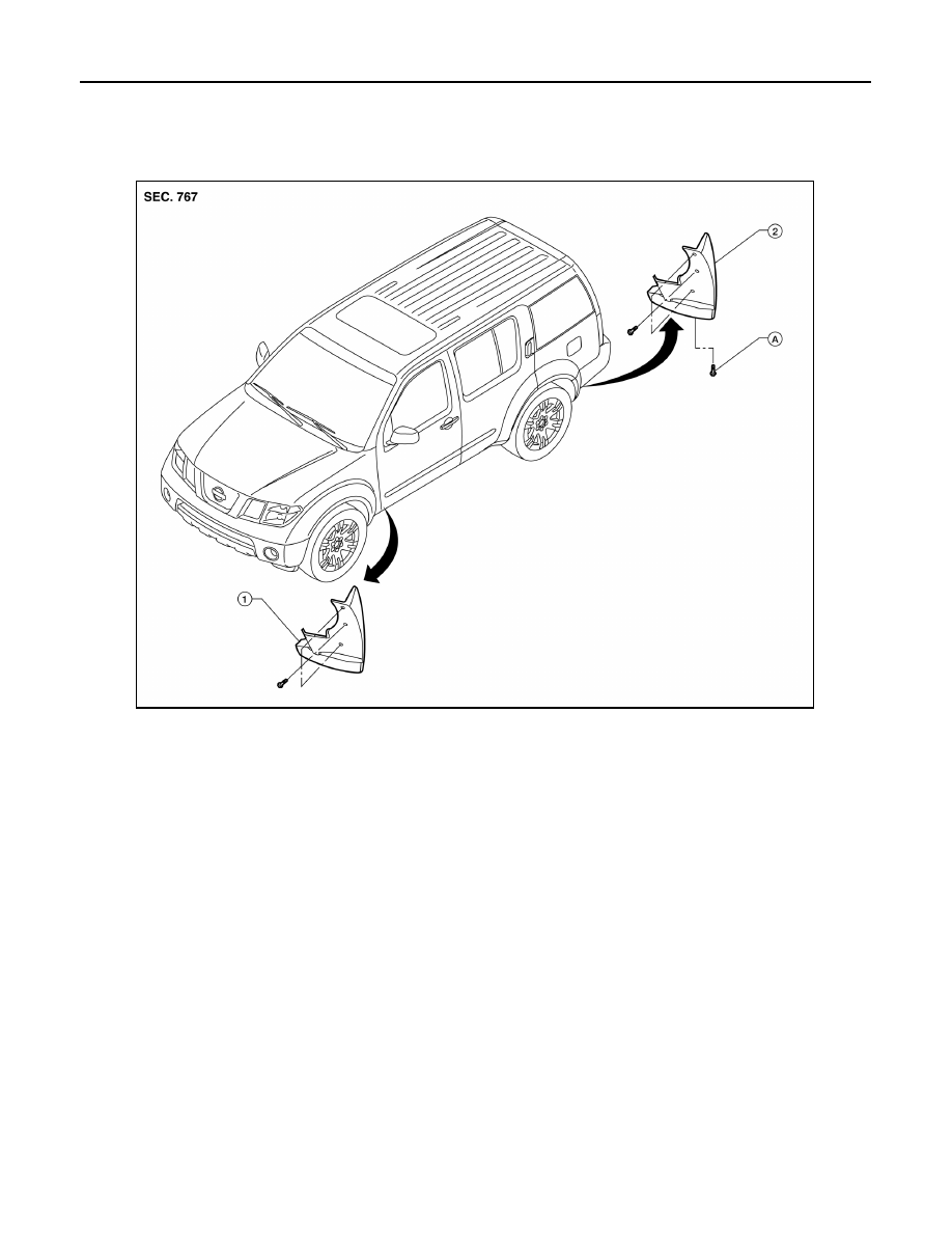
Removal and Installation
INFOID:0000000007355998
REMOVAL
1. Remove the front mudguard screws, then remove the front mudguard.
2. Remove the rear mudguard clips and screws and remove the rear mudguard.
INSTALLATION
Installation is in the reverse order of removal.
1.
Front mudguard
2.
Rear mudguard
A.
Clip C205
AWKIA1741ZZ
August 2012
2012 Pathfinder