Nissan Pathfinder (2012 year). Manual - part 367


  Index      Manuals     Nissan Pathfinder (2012 year) - Service and Repair Manual


Search            copyright infringement  


Content      ..     365      366      367      368     ..


Nissan Pathfinder (2012 year). Manual - part 367


EXL-52

< DTC/CIRCUIT DIAGNOSIS >

PARKING LAMP CIRCUIT

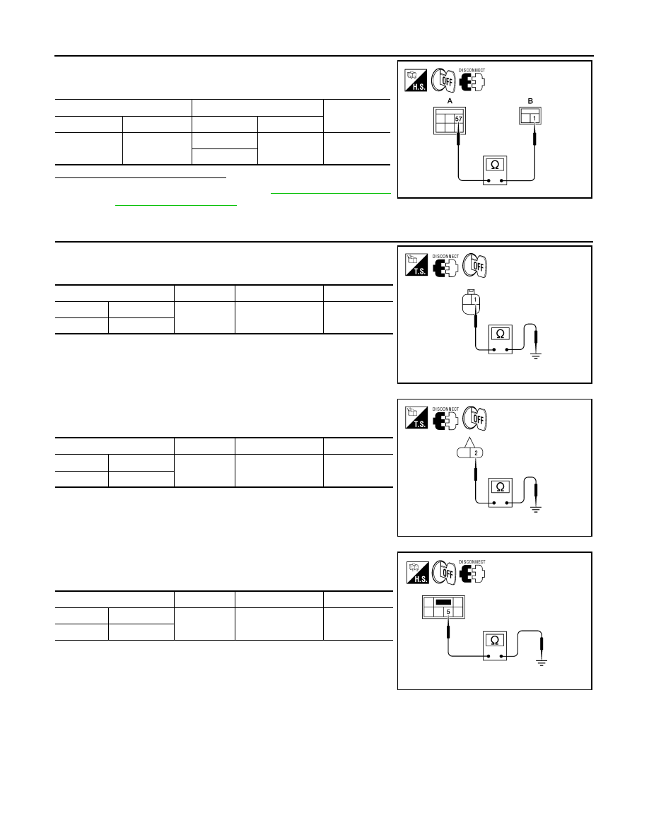
6. Check continuity between the IPDM E/R harness connector (A)

and license plate lamp connector (B). 

Are continuity results as specified?

YES

>> Replace IPDM E/R. Refer to 

PCS-29, "Removal and

Installation of IPDM E/R"

.

NO

>> Repair the harnesses or connectors.

4.

CHECK PARKING, LICENSE AND TAIL LAMP GROUND CIRCUITS

1. Check continuity between the front parking lamp harness con-

nector and ground.

2. Check continuity between the front side marker lamp harness

connector and ground.

3. Check continuity between the rear combination lamp harness

connector and ground.

A

B

Continuity

Connector

Terminal

Connector

Terminal

E124

57

D506

1

Yes

D507

ALLIA0638GB

Connector

Terminal

Continuity

LH

E27

1

Ground

Yes

RH

E111

AWLIA1676ZZ

Connector

Terminal

Continuity

LH

E17

2

Ground

Yes

RH

E108

AWLIA1677ZZ

Connector

Terminal

Continuity

LH

B35

5

Ground

Yes

RH

B105

ALLIA0641GB

August 2012

2012 Pathfinder

PARKING LAMP CIRCUIT

EXL-53

< DTC/CIRCUIT DIAGNOSIS >

C

D

E

F

G

H

I

J

K

M

A

B

EXL

N

O

P

4. Check continuity between the license plate lamp harness con-

nector and ground.

Are continuity results as specified?

YES

>> Inspect the parking lamp bulb.

NO

>> Repair the harness.

Connector

Terminal

Continuity

D506

2

Ground

Yes

D507

ALLIA0642GB

August 2012

2012 Pathfinder

EXL-54

< DTC/CIRCUIT DIAGNOSIS >

TURN SIGNAL LAMP CIRCUIT

TURN SIGNAL LAMP CIRCUIT

Description

INFOID:0000000007355159

The BCM monitors inputs from the combination switch (lighting and turn signal switch) to determine when to

activate the turn signals. The BCM outputs voltage direction to the left and right turn signals during turn signal

operation or both during hazard warning operation. The BCM sends a turn signal indicator request to the com-

bination meter via the CAN communication lines. 

The BCM performs the fast flasher operation (fail-safe) if any bulb or harness of the turn signal lamp circuit is

open.

NOTE:

Turn signal lamp blinks at normal speed when using the hazard warning lamp.

Component Function Check

INFOID:0000000007355160

1.

CHECK TURN SIGNAL LAMP

WITH CONSULT

1. Select "FLASHER" of BCM (FLASHER) active test item.

2. With operating the test items, check that the turn signal lamp blinks.

Does the turn signal lamp blink?

YES

>> Turn signal lamp circuit is normal.

NO

>> Refer to 

EXL-54, "Diagnosis Procedure"

.

Diagnosis Procedure

INFOID:0000000007355161

Regarding Wiring Diagram information, refer to 

EXL-101, "Wiring Diagram"

.

1.

CHECK TURN SIGNAL LAMP BULB

Check the applicable lamp bulb to be sure the proper bulb standard is in use and the bulb is not open.
Is the bulb OK?

YES

>> GO TO 2

NO

>> Replace the bulb.

2.

CHECK TURN SIGNAL LAMP OUTPUT VOLTAGE

1. Turn the ignition switch OFF.

2. Disconnect front combination lamp connector and rear combination lamp connector.

3. Turn the ignition switch ON.

4. With turn signal switch operating, check the voltage between the front combination lamp harness connec-

tor and ground.

LH

: Turn signal lamp LH blinking 

RH

: Turn signal lamp RH blinking 

Off

: The turn signal lamp OFF

(+)

(

)

Voltage

Connector

Terminal

E27

LH

3

Ground

E111

RH

PKID0926E

August 2012

2012 Pathfinder

TURN SIGNAL LAMP CIRCUIT

EXL-55

< DTC/CIRCUIT DIAGNOSIS >

C

D

E

F

G

H

I

J

K

M

A

B

EXL

N

O

P

5. With turn signal switch operating, check the voltage between the rear combination lamp harness connec-

tor and ground.

Is voltage reading as specified?

YES

>> GO TO 3

NO

>> GO TO 5

3.

CHECK TURN SIGNAL LAMP CIRCUIT FOR OPEN 

1. Turn the ignition switch OFF.

2. Disconnect BCM connector M20, front combination lamp con-

nector and rear combination lamp connector.

3. Check continuity between the BCM harness connector M20 (A)

and the front combination lamps harness connector (B).

4. Check continuity between the BCM harness connector M20 (A)

and the rear combination lamp harness connector (B). 

Are continuity results as specified?

YES

>> GO TO 4

NO

>> Repair the harnesses or connectors.

4.

CHECK TURN SIGNAL LAMP SHORT CIRCUIT

Check continuity between the BCM harness connector M20 and

ground.

Does continuity exist?

YES

>> Repair the harnesses or connectors.

NO

>> Replace BCM. Refer to 

BCS-53, "Removal and Installa-

tion"

.

5.

CHECK TURN SIGNAL LAMP GROUND CIRCUIT

(+)

(

)

Voltage

Connector

Terminal

B35

LH

4

Ground

B105

RH

PKID0926E

A

B

Continuity

Connector

Terminal

Connector

Terminal

Front LH

M20

60

E27

3

Yes

Front RH

61

E111

AWLIA1678ZZ

A

B

Continuity

Connector

Terminal

Connector

Terminal

Rear LH

M20

60

B35

4

Yes

Rear RH

61

B105

4

ALLIA0644GB

Connector

Terminal

Continuity

LH

M20

60

Ground

No

RH

61

ALLIA0404GB

August 2012

2012 Pathfinder

EXL-56

< DTC/CIRCUIT DIAGNOSIS >

TURN SIGNAL LAMP CIRCUIT

1. Check continuity between the front combination lamp harness

connector and ground.

2. Check continuity between the rear combination lamp harness

connector and ground.

Are continuity results as specified?

YES

>> Replace the malfunctioning lamp.

NO

>> Repair the harnesses or connectors.

Connector

Terminal

Continuity

Front LH

E27

1

Ground

Yes

Front RH

E111

AWLIA1679ZZ

Connector

Terminal

Continuity

Rear LH

B35

5

Ground

Yes

Rear RH

B105

ALLIA0641GB

August 2012

2012 Pathfinder

OPTICAL SENSOR

EXL-57

< DTC/CIRCUIT DIAGNOSIS >

C

D

E

F

G

H

I

J

K

M

A

B

EXL

N

O

P

OPTICAL SENSOR

Description

INFOID:0000000007355162

The optical sensor converts the outside brightness (lux) to voltage and transmits the optical sensor signal to

the BCM.

Component Function Check

INFOID:0000000007355163

1.

CHECK OPTICAL SENSOR SIGNAL BY CONSULT

WITH CONSULT

1. Turn the ignition switch ON.

2. Select "OPTICAL SENSOR" of BCM (HEAD LAMP) DATA MONITOR item.

3. Turn the lighting switch to AUTO.

4. With the optical sensor illuminating, check the monitor status. 

*: Illuminates the optical sensor. The value may be less than the standard value if brightness is weak.

Is the item status normal?

YES

>> Optical sensor is normal.

NO

>> Refer to 

EXL-57, "Diagnosis Procedure"

.

Diagnosis Procedure

INFOID:0000000007355164

Regarding Wiring Diagram information, refer to 

EXL-89, "Wiring Diagram"

.

1.

CHECK OPTICAL SENSOR GROUND CIRCUIT

1. Turn the ignition switch OFF.

2. Disconnect BCM connector M18 and optical sensor connector M145.

3. Check continuity between BCM harness connector and optical sensor harness connector.

4. Check continuity between BCM harness connector and ground. 

Are continuity results as specified?

YES

>> GO TO 2

NO

>> Repair harness or connector. 

2.

CHECK OPTICAL SENSOR SIGNAL CIRCUIT

1. Check continuity between BCM harness connector and optical sensor harness connector.

Monitor item

Condition

Voltage

OPTICAL SENSOR

When illuminating

3.1V or more *

When shutting off light

0.6V or less

BCM

Optical sensor

Continuity

Connector

Terminal

Connector

Terminal

M18

18

M145

3

Yes

BCM

Continuity

Connector

Terminal

M18

18

Ground

No

BCM

Optical sensor

Continuity

Connector

Terminal

Connector

Terminal

M20

58

M145

4

Yes

August 2012

2012 Pathfinder

EXL-58

< DTC/CIRCUIT DIAGNOSIS >

OPTICAL SENSOR

2. Check continuity between BCM harness connector M20 and ground.

Are the continuity results as specified?

YES

>> Replace the optical sensor. Refer to 

EXL-147, "Removal and Installation"

.

NO

>> Repair harness or connector. 

BCM

Continuity

Connector

Terminal

M20

58

Ground

No

August 2012

2012 Pathfinder

BCM (BODY CONTROL MODULE)

EXL-59

< ECU DIAGNOSIS INFORMATION >

C

D

E

F

G

H

I

J

K

M

A

B

EXL

N

O

P

ECU DIAGNOSIS INFORMATION

BCM (BODY CONTROL MODULE)

Reference Value

INFOID:0000000007827524

NOTE:

The Signal Tech II Tool (J-50190) can be used to perform the following functions. Refer to the Signal Tech II

User Guide for additional information.

• Activate and display TPMS transmitter IDs

• Display tire pressure reported by the TPMS transmitter

• Read TPMS DTCs

• Register TPMS transmitter IDs

VALUES ON THE DIAGNOSIS TOOL

Monitor Item

Condition

Value/Status

ACC ON SW

Ignition switch OFF or ON

Off

Ignition switch ACC

On

AIR COND SW

A/C switch OFF

Off

A/C switch ON

On

AIR PRESS FL

Front left tire air pressure value

kPa, kg/cm

2

, psi

AIR PRESS FR

Front right tire air pressure value

kPa, kg/cm

2

, psi

AIR PRESS RL

Rear left tire air pressure value

kPa, kg/cm

2

, psi

AIR PRESS RR

Rear right tire air pressure value

kPa, kg/cm

2

, psi

AUTO LIGHT SW

Lighting switch OFF

Off

Lighting switch AUTO

On

BACK DOOR SW

Back door closed

Off

Back door opened

On

BRAKE SW

Brake pedal released

Off

Brake pedal applied

On

BUCKLE SW

Seat belt buckle unfastened

Off

Seat belt buckle fastened

On

BUZZER

Buzzer in combination meter OFF

Off

Buzzer in combination meter ON

On

CDL LOCK SW

Door lock/unlock switch does not operate

Off

Press door lock/unlock switch to the LOCK side

On

CDL UNLOCK SW

Door lock/unlock switch does not operate

Off

Press door lock/unlock switch to the UNLOCK side

On

DOOR SW-AS

Front door RH closed

Off

Front door RH opened

On

DOOR SW-DR

Front door LH closed

Off

Front door LH opened

On

DOOR SW-RL

Rear door LH closed

Off

Rear door LH opened

On

DOOR SW-RR

Rear door RH closed

Off

Rear door RH opened

On

FAN ON SIG

Blower motor fan switch OFF

Off

Blower motor fan switch ON

On

August 2012

2012 Pathfinder


Content      ..     365      366      367      368     ..