Nissan Pathfinder (2012 year). Manual - part 313
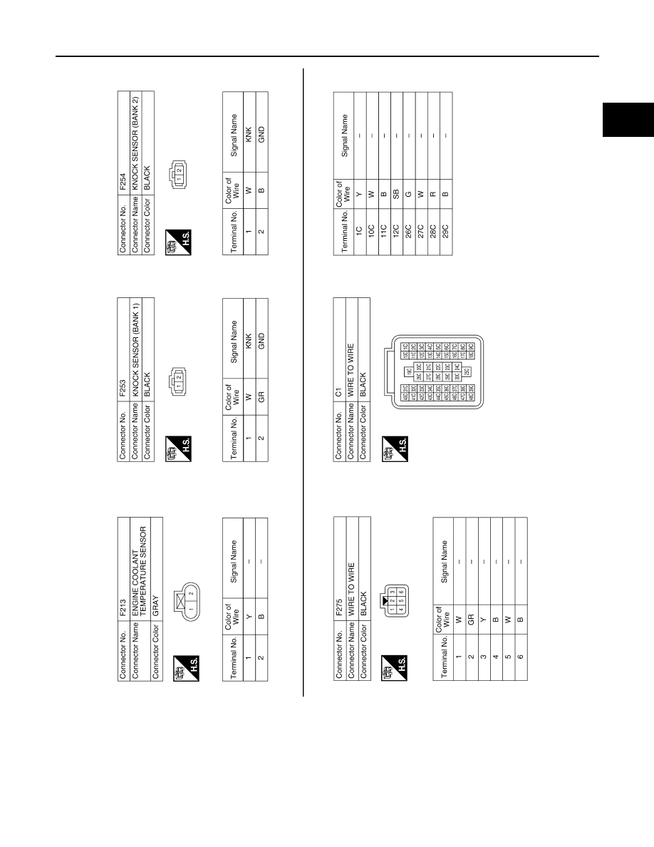
ENGINE CONTROL SYSTEM
EC-585
< WIRING DIAGRAM >
[VK56DE]
C
D
E
F
G
H
I
J
K
L
M
A
EC
N
P
O
ABBIA1111GB
August 2012
2012 Pathfinder
|
|
|
ENGINE CONTROL SYSTEM EC-585 < WIRING DIAGRAM > [VK56DE] C D E F G H I J K L M A EC N P O ABBIA1111GB August 2012 2012 Pathfinder |