Nissan Pathfinder (2012 year). Manual - part 252
POWER SUPPLY AND GROUND CIRCUIT
EC-97
< DTC/CIRCUIT DIAGNOSIS >
[VQ40DE]
C
D
E
F
G
H
I
J
K
L
M
A
EC
N
P
O
• Harness connectors F32, E2
• Harness for open or short between ECM and ground
>> Repair open circuit or short to power in harness or connectors.
16.
CHECK INTERMITTENT INCIDENT
GI-37, "Intermittent Incident"
.
OK or NG
OK
>> Replace IPDM E/R. Refer to
PCS-29, "Removal and Installation of IPDM E/R"
.
NG
>> Repair open circuit or short to power in harness or connectors.
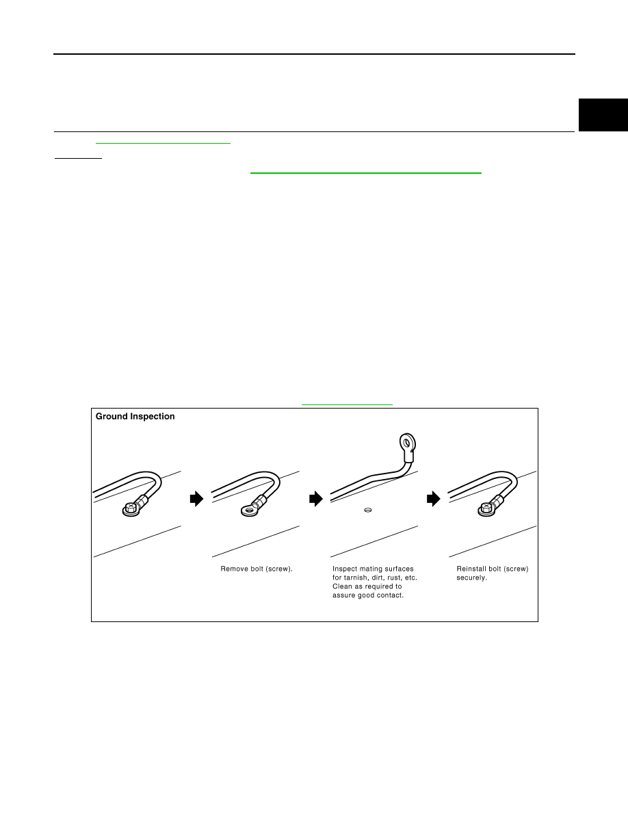
Ground Inspection
INFOID:0000000007357987
Ground connections are very important to the proper operation of electrical and electronic circuits. Ground
connections are often exposed to moisture, dirt and other corrosive elements. The corrosion (rust) can
become an unwanted resistance. This unwanted resistance can change the way a circuit works.
Electronically controlled circuits are very sensitive to proper grounding. A loose or corroded ground can drasti-
cally affect an electronically controlled circuit. A poor or corroded ground can easily affect the circuit. Even
when the ground connection looks clean, there can be a thin film of rust on the surface.
When inspecting a ground connection follow these rules:
• Remove the ground bolt or screw.
• Inspect all mating surfaces for tarnish, dirt, rust, etc.
• Clean as required to assure good contact.
• Reinstall bolt or screw securely.
• Inspect for “add-on” accessories which may be interfering with the ground circuit.
• If several wires are crimped into one ground eyelet terminal, check for proper crimps. Make sure all of the
wires are clean, securely fastened and providing a good ground path. If multiple wires are cased in one eye-
let make sure no ground wires have excess wire insulation.
For detailed ground distribution information, refer to
.
PBIB1870E
August 2012
2012 Pathfinder