Nissan Pathfinder (2012 year). Manual - part 229


  Index      Manuals     Nissan Pathfinder (2012 year) - Service and Repair Manual


Search            copyright infringement  


Content      ..     227      228      229      230     ..


Nissan Pathfinder (2012 year). Manual - part 229


FRONT FINAL DRIVE

DLN-397

< UNIT DISASSEMBLY AND ASSEMBLY >

[FRONT FINAL DRIVE: M205]

C

E

F

G

H

I

J

K

L

M

A

B

DLN

N

O

P

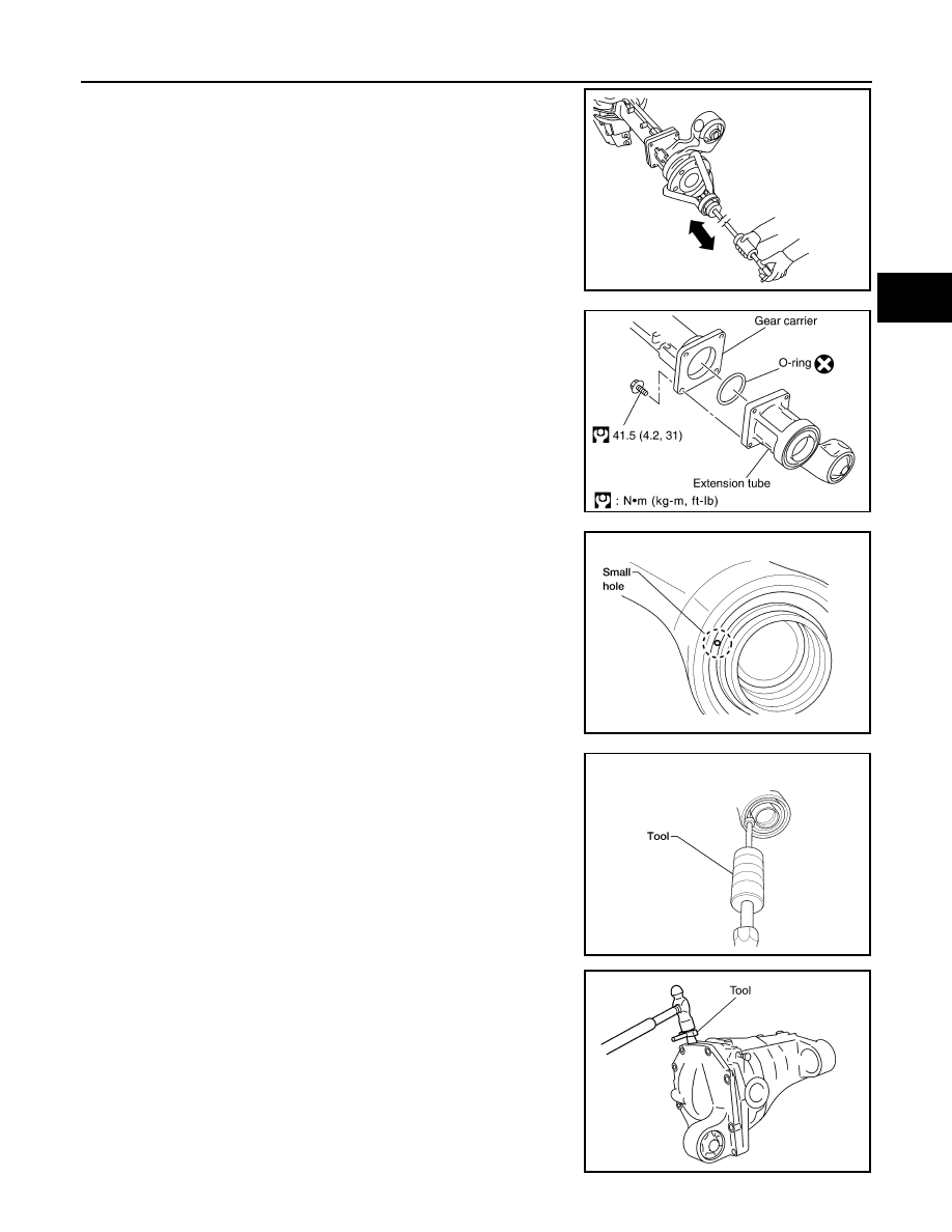
2. Remove the differential side shaft and differential side flange

using suitable tool.

3. Remove the extension tube and O-ring from the gear carrier.

CAUTION:

Do not reuse O-ring.

4. Place a small hole in the side oil seal case using suitable tool.

5. Remove the side oil seal using Tool as shown.

6. Remove the carrier cover bolts and separate the carrier cover

from the gear carrier using Tool.

CAUTION:

• Do not damage the mating surface.

• Do not insert flat-bladed screwdriver, this will damage the

mating surface.

BDIA0006E

SDIA3205E

LDIA0129E

Tool number

:  —

SP8P

LDIA0130E

Tool number

: KV10111100 (J-37228)

PDIA0699E

August 2012

2012 Pathfinder

DLN-398

< UNIT DISASSEMBLY AND ASSEMBLY >

[FRONT FINAL DRIVE: M205]

FRONT FINAL DRIVE

7. For proper reinstallation, paint matching marks on one side of

the side bearing cap and gear carrier.

CAUTION:

• For matching marks, use paint. Do not damage side bear-

ing cap or gear carrier.

• Side bearing caps are line-board during manufacture. The

matching marks are used to reinstall them in their original

positions.

8. Remove the side bearing caps.

9. Remove the side bearing adjuster.

10. Lift the differential case assembly out of the gear carrier. 

CAUTION:

Keep side bearing outer races together with side bearing

inner races. Do not mix them up.

11. Remove side bearing inner race using Tools as shown.

CAUTION:

• Do not remove side bearing inner race unless it is being

replaced.

• Place copper plates between the vise and the side bearing

inner race and drive gear to prevent damage.

• Engage puller jaws in groove to prevent damage to bear-

ing.

PDIA0700E

PDIA0701E

SDIA2230E

SPD527

Tool number

(A): ST33081000 ( — )
(B): ST30021000 ( — )

SDIA2237E

August 2012

2012 Pathfinder

FRONT FINAL DRIVE

DLN-399

< UNIT DISASSEMBLY AND ASSEMBLY >

[FRONT FINAL DRIVE: M205]

C

E

F

G

H

I

J

K

L

M

A

B

DLN

N

O

P

• Keep side bearing outer races together with side bearing

inner races. Do not mix them up.

12. For proper reinstallation, paint matching marks on the differential

case and drive gear.

CAUTION:

Use paint for matching marks. Do not damage differential

case or drive gear.

13. Remove the drive gear bolts.
14. Tap the drive gear off the differential case using suitable tool.

CAUTION:

Tap evenly all around to keep drive gear from bending.

15. Remove the lock pin of the pinion mate shaft from the drive gear

side using suitable tool.

16. Remove the pinion mate shaft.

17. Turn the pinion mate gear, then remove the pinion mate gear,

pinion mate thrust washer, side gear and side gear thrust

washer from the differential case.

SPD022

PDIA0496E

SPD025

SDIA0031J

SDIA0032J

August 2012

2012 Pathfinder

DLN-400

< UNIT DISASSEMBLY AND ASSEMBLY >

[FRONT FINAL DRIVE: M205]

FRONT FINAL DRIVE

Drive Pinion Assembly

1. Remove the differential assembly. 
2. Remove the drive pinion lock nut using suitable tool.
3. Put matching marks on the companion flange and drive pinion

using paint.

CAUTION:

Use paint to make the matching marks. Do not damage the

companion flange or drive pinion.

4. Remove the companion flange using suitable tool.

5. Press the drive pinion assembly (with rear inner bearing race

and collapsible spacer) out of the gear carrier.

CAUTION:

Do not drop drive pinion assembly.

6. Remove the drive pinion rear bearing inner race and drive pinion

height adjusting washer using Tool.

PDIA0702E

PDIA0703E

SDIA2234E

Tool number

: ST30021000 ( — )

S-PD179

August 2012

2012 Pathfinder

FRONT FINAL DRIVE

DLN-401

< UNIT DISASSEMBLY AND ASSEMBLY >

[FRONT FINAL DRIVE: M205]

C

E

F

G

H

I

J

K

L

M

A

B

DLN

N

O

P

7. Place a small hole in the front oil seal case using suitable tool.

8. Remove the front oil seal using Tool as shown.

9. Remove the drive pinion front bearing inner race.
10. Remove the drive pinion front bearing outer race using Tool as

shown. Locate the driver on the back edge of the drive pinion

front bearing outer race, then drive the drive pinion front bearing

outer race out.

CAUTION:

Do not damage gear carrier.

11. Remove the drive pinion rear bearing outer race using Tool as

shown. Locate the driver on the back edge of the drive pinion

rear bearing outer race, then drive the drive pinion rear bearing

outer race out.

CAUTION:

Do not damage gear carrier.

INSPECTION AFTER DISASSEMBLY

Clean the disassembled parts. Then inspect the parts for wear or damage. If wear or damage are found, follow

the measures below.

Drive Pinion and Drive Gear

• If the drive pinion and drive gear teeth do not mesh or line-up correctly, determine the cause and adjust,

repair, or replace as necessary.

• If the drive pinion or drive gear are worn, cracked, damaged, pitted or chipped (by friction) noticeably,

replace with new drive pinion and drive gear.

LDIA0129E

Tool number

:  —

SP8P

LDIA0130E

Tool number

(A):  —

C-4171

(B): —

D-103

LDIA0131E

Tool number

(A):  —

C-4171

(B): —

C-4307

LDIA0132E

August 2012

2012 Pathfinder

DLN-402

< UNIT DISASSEMBLY AND ASSEMBLY >

[FRONT FINAL DRIVE: M205]

FRONT FINAL DRIVE

• Drive pinion and drive gear are supplied in matched sets only. Matching numbers on both drive pinion and

drive gear are etched for verification. If a new drive pinion and drive gear set are being used, verify the num-

bers of each drive pinion and drive gear before proceeding with assembly.

Bearing

• If bearings are chipped (by friction), pitted, worn, rusted, scratched, or unusual noise is coming from bearing,

replace with new bearing assembly (as a new set).

• Bearing must be replaced with a new one whenever disassembled.

Side Gear and Pinion Mate Gear

• If any cracks or damage are found on the surface of the teeth, replace with new one.

• If any worn or chipped marks are found on the side of the side gear and pinion mate gear which contact the

thrust washer, replace with new one.

• Replace both side gear and pinion mate gear as a set when replacing side gear or pinion mate gear.

Side Gear Thrust Washer and Pinion Mate Thrust Washer

• If any chips (by friction), damage, or unusual wear are found, replace with new one.

Gear Carrier

• If any wear or cracks are found on the contact sides of gear carrier, replace with new one.

Companion Flange

• If any chips (about 0.1mm, 0.004 in) or other damage on the companion flange surface which contacts the

front oil seal lips are found, replace with new one.

ADJUSTING AND SELECTING WASHERS

Side Gear Back Clearance

• Assemble the differential parts if they are disassembled. Refer to 

DLN-393, "Exploded View"

1. Place the differential case straight up so that the side gear to be

measured is upward.

PDIA0460E

August 2012

2012 Pathfinder

FRONT FINAL DRIVE

DLN-403

< UNIT DISASSEMBLY AND ASSEMBLY >

[FRONT FINAL DRIVE: M205]

C

E

F

G

H

I

J

K

L

M

A

B

DLN

N

O

P

2. Using feeler gauges, measure the clearance between the side

gear back and differential case at three different points, while

rotating the side gear. Average the three readings to calculate

the clearance. (Measure the clearance of the other side as well.)

• If the side gear back clearance is outside of the specification,

use a thicker or thinner side gear thrust washer to adjust.

Refer to 

DLN-410, "Inspection and Adjustment"

.

CAUTION:

• Insert feeler gauges with the same thickness on both

sides to prevent side gear from tilting.

• Each gear should rotate smoothly without excessive

resistance during differential motion.

• Select a side gear thrust washer for right and left individually.

NOTE:

Side gear back clearance is clearance between side gear and differential case for adjusting side gear

backlash.

Drive Pinion Height

• Drive gear and drive pinion are supplied in matched sets only.

Matching numbers on both drive pinion and drive gear are etched

for verification. If a new gear set is being used, verify the numbers

of each drive pinion and drive gear before proceeding with assem-

bly.

• The mounting distance from the centerline of the drive gear to the back face of the drive pinion for the M205

final drive assembly is 103.5 mm (4.0748 inches).

On the button end of each drive pinion, there is etched a plus (+) number, a minus (-) number, or a zero (0),

which indicates the best running position for each particular gear set. This dimension is controlled by a

selective drive pinion height adjusting washer between the drive pinion rear bearing inner race and drive pin-

ion.

For example: If a drive pinion is etched m+8 (+3), it would require 0.08 mm (0.003 inch) less drive pinion

height adjusting washer than a drive pinion etched “0”. This means decreasing drive pinion height adjusting

washer thickness; increases the mounting distance of the drive pinion to 103.6 mm (4.0778 inches). If a

drive pinion is etched m-8 (-3), it would require adding 0.08mm (0.003 inch) more to the drive pinion height

adjusting washer than would be required if the drive pinion were etched “0”. By adding 0.08 mm (0.003 inch),

the mounting distance of the drive pinion was decreased to 103.4 mm (4.0718 inches) which is just what a

m-8 (-3) etching indicated.      

• To change the drive pinion height, use different drive pinion height adjusting washers which come in different

thickness.

• Use the following tables as a guide for selecting the correct drive pinion height adjusting washer thickness to

add or subtract from the old drive pinion height adjusting washer.

Side gear back 
clearance:

Refer to 

DLN-410, "Inspec-

tion and Adjustment"

If the side gear back clearance is greater than 
specification:

Use a thicker side gear thrust washer.

If the side gear back clearance is less than spec-
ification:

Use a thinner side gear thrust washer.

PDIA0576E

SDIA2241E

August 2012

2012 Pathfinder

DLN-404

< UNIT DISASSEMBLY AND ASSEMBLY >

[FRONT FINAL DRIVE: M205]

FRONT FINAL DRIVE

ASSEMBLY

Drive Pinion Assembly

1. Install drive pinion rear bearing outer race using Tools.

2. Install drive pinion front bearing outer race using Tools.

3. Select drive pinion height adjusting washer. Refer to 

DLN-410, "Inspection and Adjustment"

.

OLD DRIVE 

PINION 

MARKING

NEW DRIVE PINION MARKING mm (in)

-10 (-4)

-8 (-3)

-5 (-2)

-3 (-1)

0 (0)

+3 (+1)

+5 (+2)

+8 (+3)

+10 (+4)

+10 (+4)

+0.20

(+0.008)

+0.18

(+0.007) 

+0.15

(+0.006)

+0.13

(+0.005)

+0.10

(+0.004)

+0.08

(+0.003)

+0.05

(+0.002)

+0.02

(+0.001)

0

(0)

+8 (+3)

+0.18

(+0.007)

+0.15

(+0.006)

+0.13

(+0.005)

+0.10

(+0.004)

+0.08

(+0.003)

+0.05

(+0.002)

+0.02

(+0.001)

0

(0)

-0.02

(-0.001)

+5 (+2)

+0.15

(+0.006)

+0.13

(+0.005)

+0.10

(+0.004)

+0.08

(+0.003)

+0.05

(+0.002)

+0.02

(+0.001)

0

(0)

-0.02

(-0.001)

-0.05

(-0.002)

+3 (+1)

+0.13

(+0.005)

+0.10

(+0.004)

+0.08

(+0.003)

+0.05

(+0.002)

+0.02

(+0.001)

0

(0)

-0.02

(-0.001)

-0.05

(-0.002)

-0.08

(-0.003)

0 (0)

+0.10

(+0.004)

+0.08

(+0.003)

+0.05

(+0.002)

+0.02 

(+0.001)

0

(0)

-0.02

(-0.001)

-0.05

(-0.002)

-0.08

(-0.003)

-0.10

(-0.004)

-3 (-1)

+0.08

(+0.003)

+0.05

(+0.002)

+0.02

(+0.001)

0

(0)

-0.02

(-0.001)

-0.05

(-0.002)

-0.08

(-0.003)

-0.10

(-0.004)

-0.13

(-0.005)

-5 (-2)

+0.05

(+0.002)

+0.02

(+0.001)

0

(0)

-0.02

(-0.001)

-0.05

(-0.002)

-0.08

(-0.003)

-0.10

(-0.004)

-0.13

(-0.005)

-0.15

(-0.006)

-8 (-3)

+0.02

(+0.001)

0

(0)

-0.02

(-0.001)

-0.05

(-0.002)

-0.08

(-0.003)

-0.10

(-0.004)

-0.13

(-0.005)

-0.15

(-0.006)

-0.18

(-0.007)

-10 (-4)

0

(0)

-0.02

(-0.001)

-0.05

(-0.002)

-0.08

(-0.003)

-0.10

(-0.004)

-0.13

(-0.005)

-0.15

(-0.006)

-0.18

(-0.007)

-0.20

(-0.008)

Tool number 

(A): ST30901000 ( — )
(B): KV40105230 ( — )

SDIA2251E

Tool number

(A): ST35271000 ( — )
(B): KV40104810 ( — )

SDIA2252E

August 2012

2012 Pathfinder


Content      ..     227      228      229      230     ..