Nissan Pathfinder (2012 year). Manual - part 207
P1814 WAIT DETECTION SWITCH
DLN-221
< DTC/CIRCUIT DIAGNOSIS >
[TRANSFER: TX15B]
C
E
F
G
H
I
J
K
L
M
A
B
DLN
N
O
P
YES
>> Replace transfer control unit. Refer to
DLN-278, "Removal and Installation"
NO
>> Inspection End.
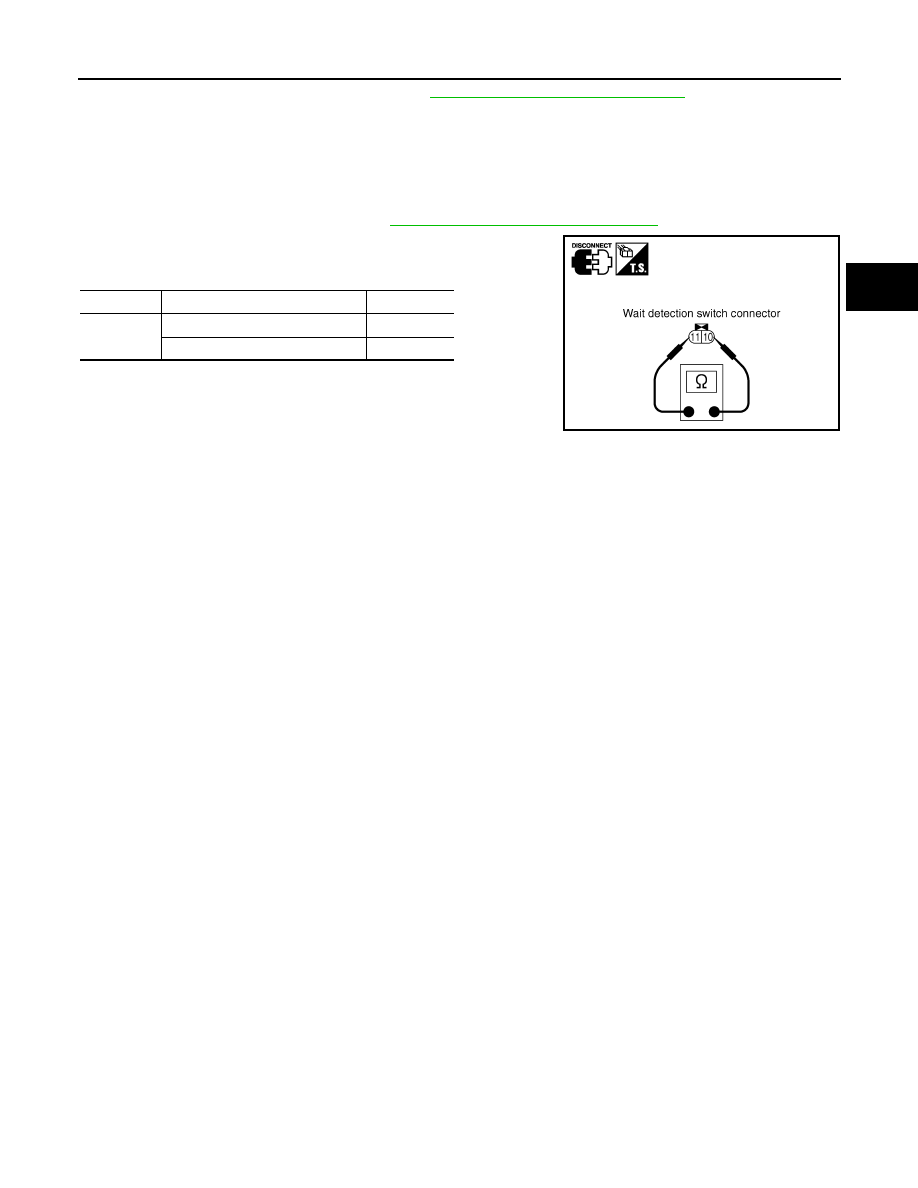
Component Inspection
INFOID:0000000007357516
1. Turn ignition switch “OFF”. (Stay for at least 5 seconds.)
2. Disconnect wait detection switch harness connector.
3. Remove wait detection switch. Refer to
DLN-198, "Component Parts Location"
.
4. Push and release wait detection switch and check continuity
between wait detection switch terminals 10 and 11.
5. If the inspection results are abnormal replace the wait detection
switch.
Terminal
Condition
Continuity
10 - 11
Push wait detection switch
Yes
Release wait detection switch
No
PDIA0208E
August 2012
2012 Pathfinder