Nissan Pathfinder (2012 year). Manual - part 149


  Index      Manuals     Nissan Pathfinder (2012 year) - Service and Repair Manual


Search            copyright infringement  


Content      ..     147      148      149      150     ..


Nissan Pathfinder (2012 year). Manual - part 149


PASSENGER SELECT UNLOCK RELAY

DLK-87

< DTC/CIRCUIT DIAGNOSIS >

[WITH INTELLIGENT KEY SYSTEM]

C

D

E

F

G

H

I

J

L

M

A

B

DLK

N

O

P

3.

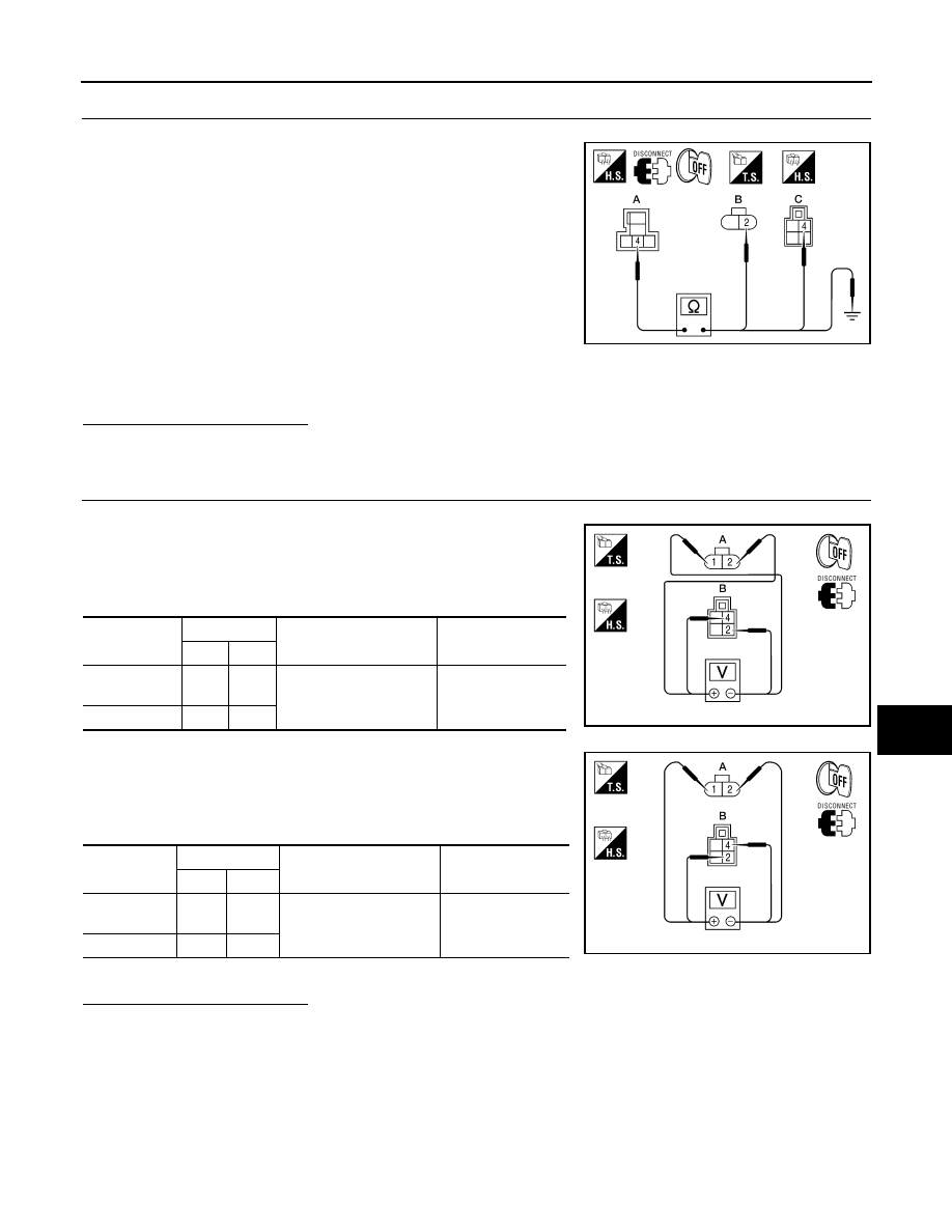
CHECK PASSENGER SELECT UNLOCK RELAY OUTPUT

1. Disconnect inoperative rear door or glass hatch lock actuator.

2. Check continuity between passenger select unlock relay con-

nector (A) M11 terminal 4 and rear door lock actuator LH con-

nector (B) D205 terminal 2 or rear door lock actuator RH

connector (B) D305 terminal 2 or glass hatch lock actuator con-

nector (C) D508 terminal 4.

3. Check continuity between passenger select unlock relay con-

nector (A) M11 terminal 4 and ground.

Is the inspection result normal?

YES

>> Replace passenger select unlock relay.

NO

>> Repair or replace harness between relay and actuator.

4.

CHECK REAR DOOR LOCK ACTUATOR ASSEMBLY

1. Reconnect BCM.

2. Check voltage between rear door lock actuator connector LH (A)

D205 terminals 1 and 2 or rear door lock actuator connector RH

(A) D305 terminals 1 and 2 or glass hatch lock actuator (B)

D508 terminals 2 and 4.

3. Check voltage between rear door lock actuator connector LH (A)

D205 terminals 1 and 2 or rear door lock actuator connector RH

(A) D305 terminals 1 and 2 or glass hatch lock actuator (B)

D508 terminals 2 and 4.

Is the inspection result normal?

YES

>> Replace rear or glass hatch lock actuator.

NO

>> Repair or replace harness between actuator and splice.

4 - 2

: Continuity should exist.

4 - 4

: Continuity should exist.

4 - Ground

: Continuity should not exist.

ALKIA1195ZZ

Connector

Terminals

Condition

Voltage (V)

(Approx.)

(+)

(-)

A: D205 (LH)

A: D305 (RH)

2

1

Main power window and 
door lock/unlock switch is 
turned to LOCK

 Battery voltage 

for 300 msec.

B: D508

4

2

ALKIA1196ZZ

Connector

Terminals

Condition

Voltage (V)

(Approx.)

(+)

(-)

A: D205 (LH)

A: D305 (RH)

1

2

Main power window and 
door lock/unlock switch is 
turned to UNLOCK

 Battery voltage 

for 300 msec.

B: D508 

2

4

ALKIA1197ZZ

August 2012

2012 Pathfinder

2012 Pathfinder

DLK-88

< DTC/CIRCUIT DIAGNOSIS >

[WITH INTELLIGENT KEY SYSTEM]

INTELLIGENT KEY WARNING BUZZER

INTELLIGENT KEY WARNING BUZZER

Description

INFOID:0000000007355464

Answers back and warns for an inappropriate operation.

Component Function Check

INFOID:0000000007355465

1.

CHECK FUNCTION

With CONSULT

Check Intelligent Key warning buzzer "OUTSIDE BUZZER" in Active Test mode.
Is the inspection result normal?

YES

>> Intelligent Key warning buzzer (engine room) is OK.

NO

>> Refer to 

DLK-88, "Diagnosis Procedure"

.

Diagnosis Procedure

INFOID:0000000007355466

Regarding Wiring Diagram information, refer to 

DLK-151, "Wiring Diagram"

.

1.

CHECK INTELLIGENT KEY WARNING BUZZER (ENGINE ROOM) POWER SUPPLY CIRCUIT

1. Turn ignition switch OFF.

2. Disconnect Intelligent Key warning buzzer (engine room) connector.

3. Check voltage between Intelligent Key warning buzzer (engine room) harness connector E60 terminal 1

and ground.

Is the inspection normal?

YES

>> GO TO 2

NO

>> Repair or replace Intelligent Key warning buzzer (engine

room) power supply circuit.

2.

CHECK INTELLIGENT KEY WARNING BUZZER (ENGINE ROOM) CIRCUIT

1. Disconnect Intelligent Key unit connector.

2. Check continuity between Intelligent Key unit harness connector

(A) M164 terminal 4 and Intelligent Key warning buzzer (engine

room) harness connector E60 terminal 3.

3. Check continuity between Intelligent Key warning buzzer

(engine room) harness connector E60 terminal 3 and ground.

Is the inspection normal?

YES

>> GO TO 3

NO

>> Repair or replace harness between Intelligent Key warning buzzer (engine room) and Intelligent

Key unit.

3.

CHECK INTELLIGENT KEY WARNING BUZZER (ENGINE ROOM) OPERATION

Check 

DLK-89, "Component Inspection"

.

1 - Ground

: Battery voltage

WIIA1195E

4 - 3

: Continuity should exist.

3 - Ground

: Continuity should not exist.

WIIA1196E

August 2012

2012 Pathfinder

2012 Pathfinder

INTELLIGENT KEY WARNING BUZZER

DLK-89

< DTC/CIRCUIT DIAGNOSIS >

[WITH INTELLIGENT KEY SYSTEM]

C

D

E

F

G

H

I

J

L

M

A

B

DLK

N

O

P

>> Inspection end.

Component Inspection

INFOID:0000000007355467

1.

CHECK INTELLIGENT KEY WARNING BUZZER

Connect battery power supply to Intelligent Key warning buzzer ter-

minals 1 and 3, and check the operation.

Is the inspection result normal?

YES

>> Inspection End.

NO

>> Replace Intelligent Key warning buzzer. 

1 (BAT+) - 3 (BAT-)

: the buzzer sounds

WIIA1197E

August 2012

2012 Pathfinder

2012 Pathfinder

DLK-90

< DTC/CIRCUIT DIAGNOSIS >

[WITH INTELLIGENT KEY SYSTEM]

INTELLIGENT KEY WARNING CHIME (COMBINATION METER)

INTELLIGENT KEY WARNING CHIME (COMBINATION METER)

Description

INFOID:0000000007355468

Answers back and warns for an inappropriate operation.

Diagnosis Procedure

INFOID:0000000007355469

1.

CHECK INTELLIGENT KEY WARNING CHIME (COMBINATION METER) OPERATION

With CONSULT

Check Intelligent Key warning buzzer "INSIDE BUZZER" in Active Test mode.
Is the inspection result normal?

YES

>> Intelligent Key warning chime (combination meter) is OK.

NO

>> Refer to 

MWI-4, "Work Flow"

.

August 2012

2012 Pathfinder

2012 Pathfinder

WARNING LAMP

DLK-91

< DTC/CIRCUIT DIAGNOSIS >

[WITH INTELLIGENT KEY SYSTEM]

C

D

E

F

G

H

I

J

L

M

A

B

DLK

N

O

P

WARNING LAMP

KEY (GREEN)
KEY (GREEN) : Description

INFOID:0000000007355470

Illuminates when the ignition knob is pushed with the presence of the Intelligent Key indicating normal opera-

tion.

KEY (GREEN) : "KEY" Warning Lamp (GREEN) Check

INFOID:0000000007355471

1.

CHECK WARNING LAMP OPERATION

 With CONSULT

• Check “INDICATOR” in “ACTIVE TEST” mode with CONSULT.

• Select “BLUE ON”.

“KEY” warning lamp (green) should illuminate.

 Without CONSULT

1. Turn ignition switch OFF.

2. Ensure Intelligent Key is in your possession inside the vehicle.

3. While monitoring the combination meter warning lamps, push the ignition knob switch.

4. The "KEY" warning lamp (green) should illuminate indicating that the Intelligent Key is nearby.

Is the inspection result normal?

YES

>> Inspection End.

NO

>> Check combination meter. Refer to 

MWI-4, "Work Flow"

.

KEY (RED)
KEY (RED) : Description

INFOID:0000000007355472

Illuminates when the ignition knob is pushed without the presence of the Intelligent Key indicating inappropri-

ate operation.

KEY (RED) : "KEY" Warning Lamp (RED) Check

INFOID:0000000007355473

1.

CHECK WARNING LAMP OPERATION

 With CONSULT

• Check “INDICATOR” in “ACTIVE TEST” mode with CONSULT.

• Select “RED ON”.

“KEY” warning lamp (red) should illuminate.

 Without CONSULT

1. Turn ignition switch OFF.

2. Ensure Intelligent Key is outside and away from the vehicle.

3. While monitoring the combination meter warning lamps, push the ignition knob switch.

4. The "KEY" warning lamp (red) should illuminate indicating that the Intelligent Key is not nearby.

Is the inspection result normal?

YES

>> Inspection End.

NO

>> Check combination meter. Refer to 

MWI-4, "Work Flow"

.

WARNING LAMP
WARNING LAMP : Description P-SHIFT

INFOID:0000000007355474

Illuminates when the ignition knob is turned from ON to OFF with the shift lever out-of-park indicating inappro-

priate operation.

August 2012

2012 Pathfinder

2012 Pathfinder

DLK-92

< DTC/CIRCUIT DIAGNOSIS >

[WITH INTELLIGENT KEY SYSTEM]

WARNING LAMP

WARNING LAMP : "P-SHIFT" Warning Lamp Check

INFOID:0000000007355475

1.

CHECK WARNING LAMP OPERATION

 With CONSULT

• Check “INDICATOR” in “ACTIVE TEST” mode with CONSULT.

• Select “KNOB ON”.

“P-SHIFT” warning lamp should illuminate.

 Without CONSULT

1. Turn ignition switch OFF.

2. While monitoring the combination meter warning lamps, turn ignition switch ON. "P-SHIFT" warning lamp

should illuminate for 1 second to perform a bulb check.

Is the inspection result normal?

YES

>> Inspection End.

NO

>> Check combination meter. Refer to 

MWI-4, "Work Flow"

.

August 2012

2012 Pathfinder

2012 Pathfinder

OUTSIDE KEY ANTENNA

DLK-93

< DTC/CIRCUIT DIAGNOSIS >

[WITH INTELLIGENT KEY SYSTEM]

C

D

E

F

G

H

I

J

L

M

A

B

DLK

N

O

P

OUTSIDE KEY ANTENNA

Description

INFOID:0000000007355476

Detects whether the Intelligent Key is in the operating range of the outside antennas.

Front outside antennas are integrated in front outside door handles (driver side, passenger side) to allow lock-

ing and unlocking of door locks when the Intelligent Key is present.

Rear bumper antenna is mounted on the rear bumper and is used to allow locking and unlocking of door locks

when the Intelligent Key is present.

Component Function Check

INFOID:0000000007355477

NOTE:

The Signal Tech II Tool (J-50190) can be used to perform the following functions. Refer to the Signal Tech II

User Guide for additional information.

• Check Intelligent Key relative signal strength

• Confirm vehicle Intelligent Key antenna signal strength

1.

CHECK DOOR REQUEST SWITCH

Check that door request switches operate normally.

Is the inspection result normal?

YES

>> GO TO 2

NO

>> Inspect door request switches. Refer to 

DLK-72, "FRONT DOOR REQUEST SWITCH :

Component Function Check"

.

2.

CHECK FRONT ANTENNAS FUNCTION

Be sure that Intelligent Key is in each outside key antenna detection range.
Does door lock/unlock when each request switch is pressed?

YES

>> Outside key antenna is OK.

NO

>> Refer to 

DLK-93, "Diagnosis Procedure"

.

Diagnosis Procedure

INFOID:0000000007355478

NOTE:

The Signal Tech II Tool (J-50190) can be used to perform the following functions. Refer to the Signal Tech II

User Guide for additional information.

• Check Intelligent Key relative signal strength

• Confirm vehicle Intelligent Key antenna signal strength

Regarding Wiring Diagram information, refer to 

DLK-151, "Wiring Diagram"

.

1.

CHECK OUTSIDE KEY ANTENNA INPUT SIGNAL

1. Turn ignition switch OFF.

2. Check signal between Intelligent Key unit connector M164 terminals 17, 19, 37 and ground with an oscil-

loscope.

August 2012

2012 Pathfinder

2012 Pathfinder

DLK-94

< DTC/CIRCUIT DIAGNOSIS >

[WITH INTELLIGENT KEY SYSTEM]

OUTSIDE KEY ANTENNA

Is the inspection result normal?

YES

>> Outside key antenna is OK.

NO

>> GO TO 2

2.

CHECK OUTSIDE KEY ANTENNA CIRCUIT

1. Disconnect Intelligent Key unit connector and outside key antenna connector.

2. Check continuity between each outside key antenna harness connector (B) D15 (driver side) or D115

(passenger side), rear bumper antenna connector (C) C127 terminals 1, 2 and Intelligent Key unit harness

connector (A) M164 terminals 17, 18, 19, 20, 37, and 38.

3. Check continuity between each outside key antenna harness

connector terminals 1, 2 and ground.

Is the inspection result normal?

YES

>> GO TO 3

NO

>> Repair or replace harness between outside key antenna and Intelligent Key unit.

3.

CHECK OUTSIDE KEY ANTENNA POWER SUPPLY

1. Replace outside key antenna. (New antenna or other antenna)

2. Connect Intelligent Key unit connector and outside key antenna connector.

Connector

Item

Terminals

Condition

Signal

(Reference value)

(+)

(-)

M164

Rear 
bumper 
antenna

17

Ground

Request 
switch is 
pushed

Front out-
side an-
tenna LH

19

Front out-
side an-
tenna RH

37

WIIA1198E

SIIA1910J

Item

Connector

Terminal

Connector

Terminal

Continuity

Rear bumper 

antenna

C: C127

1

A: M164

17

Yes

2

18

Front outside 

antenna LH

B: D15

2

19

1

20

Front outside 

antenna RH

B: D115

2

37

1

38

Item

Connector

Terminal

Continuity

Rear bumper antenna

C: C127

1

Ground

No

2

Front outside antenna 

LH

B: D15

1

2

Front outside antenna 

RH

B: D115

1

2

ALKIA1198ZZ

August 2012

2012 Pathfinder

2012 Pathfinder


Content      ..     147      148      149      150     ..