Nissan Pathfinder (2012 year). Manual - part 132


  Index      Manuals     Nissan Pathfinder (2012 year) - Service and Repair Manual


Search            copyright infringement  


Content      ..     130      131      132      133     ..


Nissan Pathfinder (2012 year). Manual - part 132


WATER PUMP

CO-53

< REMOVAL AND INSTALLATION >

[VK56DE]

C

D

E

F

G

H

I

J

K

L

M

A

CO

N

P

O

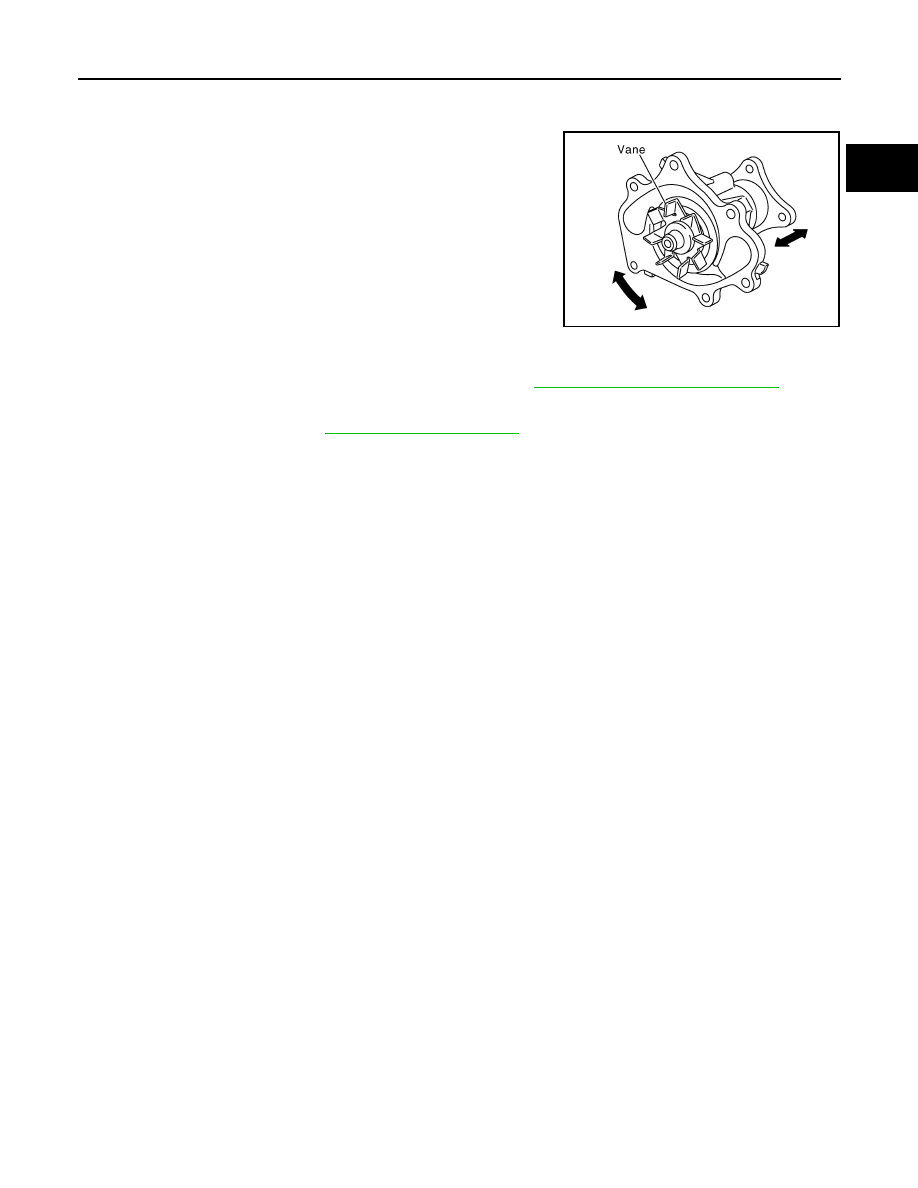
Handle water pump vane so that it does not contact any other parts.

INSPECTION AFTER REMOVAL

• Visually check that there is no significant dirt or rust on the water

pump body and vane.

• Check that the vane shaft is not loose and turns smoothly when

rotated by hand.

• Replace the water pump, if necessary.

INSTALLATION

Installation is in the reverse order of removal.

• After installation bleed the air from the cooling system. Refer to 

CO-42, "Changing Engine Coolant"

.

INSPECTION AFTER INSTALLATION

• Check for coolant leaks. Refer to 

CO-41, "System Inspection"

.

• Start and warm up engine. Visually check for coolant leaks. Repair as necessary.

KBIA2552E

August 2012

2012 Pathfinder

CO-54

< REMOVAL AND INSTALLATION >

[VK56DE]

THERMOSTAT AND WATER PIPING

THERMOSTAT AND WATER PIPING

Exploded View

INFOID:0000000007357939

Removal and Installation

INFOID:0000000007357940

WARNING:

Never remove the radiator cap when the engine is hot. Serious burns could occur from high pressure

engine coolant escaping from the radiator. Wrap a thick cloth around the cap. Slowly turn it a quarter

of a turn to release built-up pressure. Carefully remove radiator cap by turning it all the way.

NOTE:

When removing components such as hoses, tubes/lines, etc., cap or plug openings to prevent fluid from spill-

ing.

REMOVAL

Removal of Thermostat

1. Remove engine under cover. Refer to 

EXT-15, "Removal and Installation"

.

2. Partially drain engine coolant from the radiator. Refer to 

CO-42, "Changing Engine Coolant"

.

CAUTION:

• Perform this step when engine is cold.

• Do not spill engine coolant on drive belts.

3. Remove the engine room cover (if equipped). Refer to 

EM-163, "Removal and Installation"

.

4. Remove the air duct and resonator assembly. Refer to 

EM-164, "Removal and Installation"

.

KBIA2501E

1.

Heater pipe

2.

Gasket

3.

Water outlet

4.

Gasket

5.

O-ring

6.

O-ring

7.

Thermostat housing

8.

Rubber ring

9.

Thermostat

10.

Water inlet

11.

Water suction hose

12. Water suction pipe

13.

Gasket

14. Heater pipe

August 2012

2012 Pathfinder

THERMOSTAT AND WATER PIPING

CO-55

< REMOVAL AND INSTALLATION >

[VK56DE]

C

D

E

F

G

H

I

J

K

L

M

A

CO

N

P

O

5. Disconnect the water suction hose from the water inlet.
6. Remove the water inlet and thermostat.

Removal of Thermostat Housing, Water Outlet and Heater Pipe

1. Remove the intake manifold. Refer to 

EM-165, "Removal and Installation"

.

2. Remove the thermostat. Refer to 

CO-54

3. Remove upper radiator hose.
4. Remove the thermostat housing, water outlet and heater pipe.

INSPECTION AFTER REMOVAL

1. Check valve seating condition at room temperature. It should seat tightly.
2. Check valve operation.

• Place a thread so that it is caught in the valve of the thermo-

stat. Immerse fully in a container filled with water. Heat while

stirring.

• The valve opening temperature is the temperature at which

the valve opens and falls from the thread. 

• Continue heating. Check the full-open lift amount.

NOTE:

The full-open lift amount standard temperature is the reference

value.

• After checking the full-open lift amount, lower the water tem-

perature and check the valve closing temperature.

If valve seating at measured values are out of standard range, replace water inlet and thermostat assembly.

INSTALLATION

Installation is in the reverse order of removal.

CAUTION:

Do not spill engine coolant in engine room. Use a shop cloth to absorb engine coolant.

Installation of Thermostat 

• Install the thermostat with the whole circumference of each flange

part fit securely inside the rubber ring as shown. 

• Install the thermostat with the jiggle valve facing upwards. 

Installation of Water Outlet Pipe and Heater Pipe

Apply mild soap to the O-ring before inserting water pipe or heater pipes. 

CAUTION:

Do not reuse O-rings.

INSPECTION AFTER INSTALLATION

• Check for coolant leaks. Refer to 

CO-41, "System Inspection"

.

• Start and warm up the engine. Visually check for coolant leaks. Repair as necessary.

SLC252B

Thermostat

Standard

Valve opening temperature

Refer to 

CO-56, "Standard and Limit"

Full-open lift amount

Refer to 

CO-56, "Standard and Limit"

Valve closing temperature

Refer to 

CO-56, "Standard and Limit"

KBIA2502E

August 2012

2012 Pathfinder

CO-56

< SERVICE DATA AND SPECIFICATIONS (SDS) 

[VK56DE]

SERVICE DATA AND SPECIFICATIONS (SDS)

SERVICE DATA AND SPECIFICATIONS (SDS)

SERVICE DATA AND SPECIFICATIONS (SDS)

Standard and Limit

INFOID:0000000007357941

ENGINE COOLANT CAPACITY (APPROXIMATE)

Unit:   (US qt, Imp qt)

RADIATOR

Unit: kPa (kg/cm

2

, psi)

THERMOSTAT

Engine coolant capacity (With reservoir tank at "MAX" level)

13.4 (14-1/8, 11-3/4)

Reservoir cap relief pressure

Standard

98 - 118 (1.0- 1.2, 14 - 17)

Test pressure

137 (1.4, 20)

Valve opening temperature

80 - 84

°

C (176 - 183

°

F)

Full-open lift amount

More than 10 mm/95

°

C (0.39 in/203

°

F)

Valve closing temperature

77

°

C (171

°

F) or higher

August 2012

2012 Pathfinder

DEF-1

DRIVER CONTROLS

C

D

E

F

G

H

I

J

K

M

SECTION 

DEF

A

B

DEF

N

O

P

CONTENTS

DEFOGGER

BASIC INSPECTION  ....................................

3

DIAGNOSIS AND REPAIR WORKFLOW  ..........

3

Repair Work Flow ......................................................

3

SYSTEM DESCRIPTION  ..............................

4

REAR WINDOW DEFOGGER SYSTEM .............

4

System Diagram ........................................................

4

System Description  ...................................................

4

Component Parts Location ........................................

5

Component Description .............................................

5

DIAGNOSIS SYSTEM (BCM)  .............................

6

COMMON ITEM ...........................................................

6

COMMON ITEM : CONSULT Function (BCM - 
COMMON ITEM) .....................................................
..

6

REAR WINDOW DEFOGGER .....................................

7

REAR WINDOW DEFOGGER : CONSULT Func-
tion (BCM - REAR DEFOGGER)  ............................
..

7

DTC/CIRCUIT DIAGNOSIS  ..........................

8

REAR WINDOW DEFOGGER SWITCH  .............

8

Description ................................................................

8

Component Function Check ......................................

8

Diagnosis Procedure A/C and AV Switch Assem-
bly ............................................................................
..

8

Diagnosis Procedure Front Air Control  .....................

9

REAR WINDOW DEFOGGER RELAY  ..............

10

Description ..............................................................

10

Component Function Check ....................................

10

Diagnosis Procedure ...............................................

10

REAR WINDOW DEFOGGER POWER SUP-
PLY AND GROUND CIRCUIT ............................

12

Description ..............................................................

12

Component Function Check ....................................

12

Diagnosis Procedure ...............................................

12

Component Inspection  ............................................

13

DOOR MIRROR DEFOGGER LH  .....................

14

Description ...............................................................

14

Component Function Check  ....................................

14

Diagnosis Procedure  ...............................................

14

Component Inspection .............................................

16

DOOR MIRROR DEFOGGER RH .....................

17

Description ...............................................................

17

Component Function Check  ....................................

17

Diagnosis Procedure  ...............................................

17

Component Inspection .............................................

19

ECU DIAGNOSIS INFORMATION ..............

20

BCM (BODY CONTROL MODULE)  .................

20

Reference Value ......................................................

20

Terminal Layout .......................................................

23

Physical Values  .......................................................

23

WIRING DIAGRAM ......................................

29

REAR WINDOW DEFOGGER  ..........................

29

Wiring Diagram ........................................................

29

SYMPTOM DIAGNOSIS  ..............................

36

REAR WINDOW DEFOGGER AND DOOR 
MIRROR DEFOGGER DO NOT OPERATE.  ....

36

Diagnosis Procedure  ...............................................

36

REAR WINDOW DEFOGGER DOES NOT 
OPERATE BUT BOTH OF DOOR MIRROR 
DEFOGGER OPERATE. ...................................

37

Diagnosis Procedure  ...............................................

37

BOTH DOORS MIRROR DEFOGGER DON’T 
OPERATE BUT REAR WINDOW DEFOG-
GER OPERATES  ..............................................

38

Diagnosis Procedure  ...............................................

38

DRIVER SIDE DOOR MIRROR DEFOGGER 
DOES NOT OPERATE. .....................................

40

August 2012

2012 Pathfinder

DIAGNOSIS AND REPAIR WORKFLOW

DEF-3

< BASIC INSPECTION >

C

D

E

F

G

H

I

J

K

M

A

B

DEF

N

O

P

BASIC INSPECTION

DIAGNOSIS AND REPAIR WORKFLOW

Repair Work Flow

INFOID:0000000007355311

DETAILED FLOW

1.

 LISTEN TO CUSTOMER COMPLAINT

Listen to customer complaint. Get detailed information about the conditions and environment when the symp-

tom occurs.

>> GO TO 2

2.

 VERIFY THE SYMPTOM WITH OPERATIONAL CHECK

Verify the symptom with operational check.  

>> GO TO 3

3.

 GO TO APPROPRIATE TROUBLE DIAGNOSIS

Go to appropriate trouble diagnosis. 

>> GO TO 4

4.

 REPAIR OR REPLACE

Repair or replace the specific parts.

>> GO TO 5

5.

 FINAL CHECK

Final check.
Is inspection result normal?

YES

>> Inspection End

NO

>> Refer to 

GI-37, "Intermittent Incident"

.

August 2012

2012 Pathfinder

DEF-4

< SYSTEM DESCRIPTION >

REAR WINDOW DEFOGGER SYSTEM

SYSTEM DESCRIPTION

REAR WINDOW DEFOGGER SYSTEM

System Diagram

INFOID:0000000007355312

System Description

INFOID:0000000007355313

Operation Description

• When rear window defogger switch is turned ON while ignition switch is ON, the A/C and AV switch assem-

bly (with auto A/C) or front air control (without auto A/C) transmits rear window defogger switch signal to

BCM.

• BCM transmits rear window defogger control signal to IPDM E/R and display unit (with auto A/C only) via

CAN communication when rear window defogger operates.

• IPDM E/R turns rear window defogger relay and heated mirror relay (if equipped) ON when rear window

defogger switch signal is received.

• Rear window defogger and door mirror defogger (if equipped) are supplied with power and operate when

rear window defogger relay and heated mirror relay (if equipped) turn ON.

• Rear window defogger ON is displayed when signal is received.

Timer function

• BCM turns rear window defogger relay and heated mirror relay (if equipped) ON for approximately 15 min-

utes when rear window defogger switch is turned ON while ignition switch is ON. It makes rear window

defogger and door mirror defogger (if equipped) operate.

• Timer is canceled after pressing rear window defogger switch again during timer operation. Then BCM turns

rear window defogger relay and heated mirror relay (if equipped) OFF. The same reaction also occurs during

timer operation, if the ignition switch is turned OFF. 

INPUT/OUTPUT SIGNAL CHART

ALLIA1046GB

Switch

Input signal to BCM

BCM function

Actuator

Rear window defogger switch

Defogger switch signal

Rear window defogger & door mirror 

defogger (if equipped) control

Rear window defogger

Door mirror defogger (if 

equipped)

Ignition switch

Ignition signal

August 2012

2012 Pathfinder


Content      ..     130      131      132      133     ..