Nissan Pathfinder (2012 year). Manual - part 91


  Index      Manuals     Nissan Pathfinder (2012 year) - Service and Repair Manual


Search            copyright infringement  


Content      ..     89      90      91      92     ..


Nissan Pathfinder (2012 year). Manual - part 91


FRONT DISC BRAKE

BR-55

< UNIT DISASSEMBLY AND ASSEMBLY >

C

D

E

G

H

I

J

K

L

M

A

B

BR

N

O

P

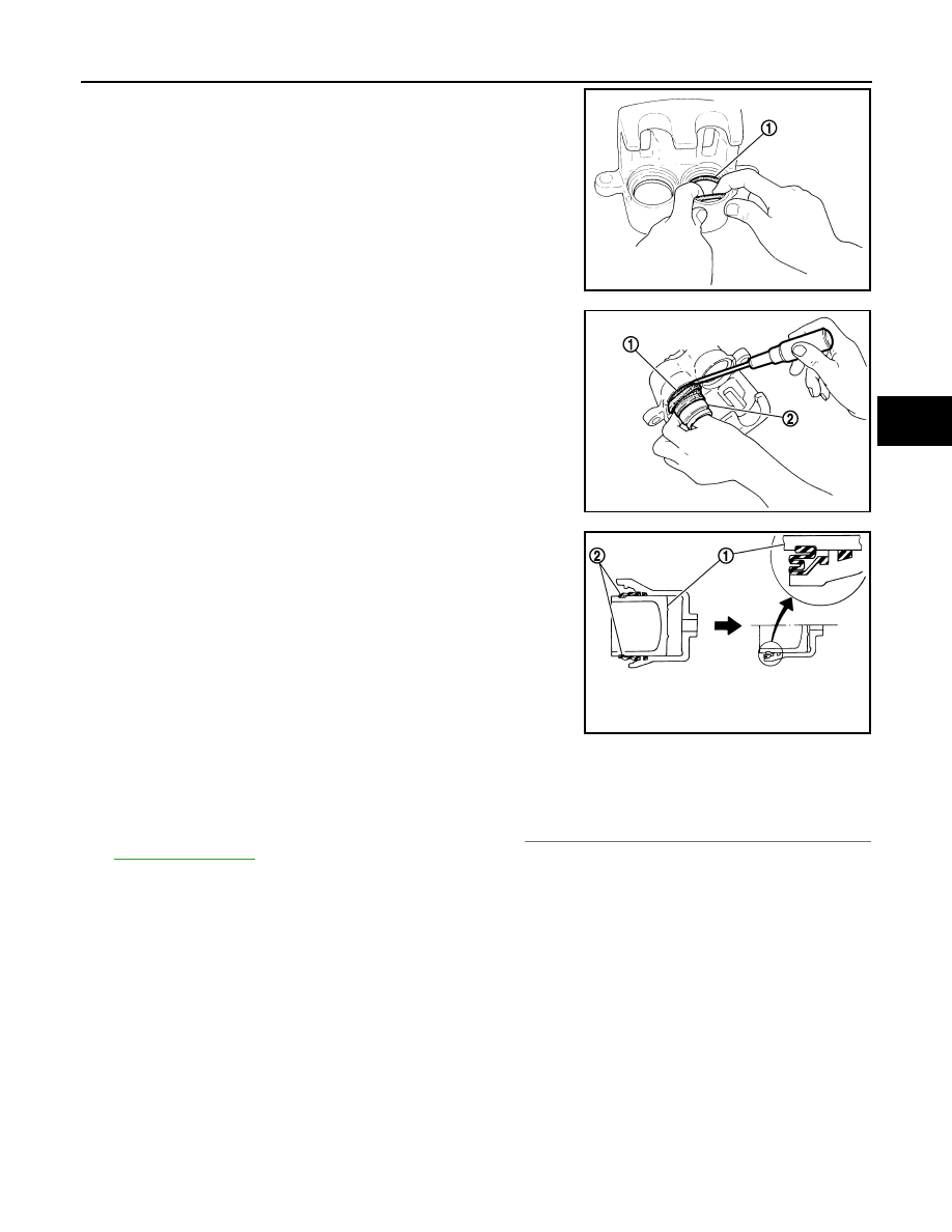
2. Apply rubber grease to the new piston seals (1) and insert the

new piston seals (1) into the groove on the cylinder body.

CAUTION:

Do not reuse piston seals.

3. Apply rubber grease to the new piston boots (1). Cover the pis-

ton end (2) with the piston boot (1), and then install the cylinder

side lip on the piston boot (1) securely into the groove on the cyl-

inder body.

CAUTION:

• Do not reuse piston boot.

• Press pistons in evenly and vary the pressing points to

prevent the cylinder inner wall from being damaged.

4. Install the pistons (1) into the cylinder body and insert the piston

boots (2) side lip into the piston groove as shown. 

CAUTION:

Press pistons in evenly and vary the pressing points to pre-

vent the cylinder inner wall from being damaged.

5. Apply rubber grease to the sliding pin boots, then install the new upper sliding pin, lower sliding pin, and

sliding pin boots on the torque member.

CAUTION:

Upper sliding pin must be replaced at each service.

6. Install the cylinder body on the torque member. Refer to 

BR-42, "Removal and Installation of Brake Cali-

per and Disc Rotor"

.

JPFIA0032ZZ

JPFIA0033ZZ

JPFIA0034ZZ

August 2012

2012 Pathfinder

BR-56

< UNIT DISASSEMBLY AND ASSEMBLY >

REAR DISC BRAKE

REAR DISC BRAKE

Exploded View of Brake Caliper

INFOID:0000000007356640

Rear Disc Brake Caliper

WARNING:

Clean dust on caliper and brake pad with a vacuum dust collector to minimize the hazard of airborne

particles or other materials.

CAUTION:

• While removing caliper body never depress brake pedal because piston will pop out. 

• It is not necessary to remove bolts on torque member and brake hose except for disassembly or

replacement of caliper body. In this case, hang caliper body with a wire so as not to stretch the brake

hose.

• Do not damage the piston boot.

• If any shim is subject to serious corrosion, replace it with a new one.

• Always replace shim and shim cover as a set when replacing brake pads.

• Keep rotor free from grease and brake fluid.

• Burnish the brake contact surface after refinishing or replacing rotors, after replacing pads, or if a

soft pedal occurs at very low mileage. Refer to 

BR-46, "Brake Burnishing"

.

Disassembly and Assembly

INFOID:0000000007356641

DISASSEMBLY

1. Remove the cylinder body. Refer to 

BR-47, "Removal and Installation of Brake Caliper and Disc Rotor"

.

2. Remove the sliding pins and boots from the torque member.

AWFIA0471GB

1.

Union bolt

2.

Brake hose

3.

Copper sealing washers

4.

Sliding pin bolt

5.

Cap

6.

Bleed valve

7.

Caliper body

8.

Sliding pin

9.

Piston seal

10. Piston

11. Piston boot

12. Torque member

13. Torque member bolt

14. Sliding pin boot

R.

Rubber grease

August 2012

2012 Pathfinder

REAR DISC BRAKE

BR-57

< UNIT DISASSEMBLY AND ASSEMBLY >

C

D

E

G

H

I

J

K

L

M

A

B

BR

N

O

P

3. Place a wooden block in the cylinder body and blow air into the

union bolt hole to remove the piston and piston boot as shown.

WARNING:

Do not get your fingers caught between the piston and

wooden block.

4. Remove the piston boot from the piston.

CAUTION:

Do not reuse piston boot.

5. Remove piston seal from cylinder body, using a suitable tool.

CAUTION:

Be careful not to damage cylinder body inner wall.

6. Remove the bleed valve and cap.

CALIPER INSPECTION

Cylinder Body

• Check inside surface of cylinder for score, rust wear, damage or foreign materials. If any of the above condi-

tions are observed, replace cylinder body.

• Minor damage from rust or foreign materials may be eliminated by polishing surface with a fine emery paper.

Replace cylinder body if necessary.

CAUTION:

• Use new brake fluid for cleaning. Do not use mineral oils such as gasoline or kerosene. 

Torque Member

Check the torque member for wear, cracks, and damage. If damage or deformation is present, replace the

torque member.

Piston

Check the piston for score, rust, wear, damage or presence of foreign materials. Replace if any of the above

conditions are observed. 

CAUTION:

Piston sliding surface is plated, do not polish with emery paper even if rust or foreign materials are

stuck to sliding surface.

Sliding Pin Bolts and Sliding Pin Boots

Check the sliding pins and sliding pin boots for wear, damage, and cracks. If damage or deformation is

present, replace the affected part.

ASSEMBLY

CAUTION:

Use NISSAN Rubber Grease when assembling.

1. Install the bleed valve and cap.

BRD0041D

JPFIA0038ZZ

August 2012

2012 Pathfinder

BR-58

< UNIT DISASSEMBLY AND ASSEMBLY >

REAR DISC BRAKE

2. Apply rubber grease to the new piston seal (1) and insert the

new piston seal (1) into the groove on the cylinder body.

CAUTION:

Do not reuse piston seal.

3. Apply rubber grease to the new piston boot (1). Cover the piston

end (2) with the piston boot (1), and then install the cylinder side

lip on the piston boot (1) securely into the groove on the cylinder

body.

CAUTION:

• Do not reuse piston boot.

• Press pistons in evenly and vary the pressing points to

prevent the cylinder inner wall from being damaged.

4. Install the piston (1) into the cylinder body and insert the piston

boot (2) side lip into the piston groove as shown. 

CAUTION:

Press pistons in evenly and vary the pressing points to pre-

vent the cylinder inner wall from being damaged.

5. Apply rubber grease to the sliding pin boots, then install the sliding pins and sliding pin boots on the torque

member.

6. Install the cylinder body on the torque member. Refer to 

BR-47, "Removal and Installation of Brake Cali-

per and Disc Rotor"

.

JPFIA0039ZZ

JPFIA0040ZZ

JPFIA0041ZZ

August 2012

2012 Pathfinder

SERVICE DATA AND SPECIFICATIONS (SDS)

BR-59

< SERVICE DATA AND SPECIFICATIONS (SDS) 

C

D

E

G

H

I

J

K

L

M

A

B

BR

N

O

P

SERVICE DATA AND SPECIFICATIONS (SDS)

SERVICE DATA AND SPECIFICATIONS (SDS)

General Specification

INFOID:0000000007356642

Unit: mm (in)

Brake Pedal

INFOID:0000000007356643

ADJUSTABLE PEDAL

Unit: mm (in)

Application

VQ40DE

VK56DE

Front brake

Brake model

CLZ33VB

Rotor outer diameter 

×

 thickness

296 

×

 28 (11.654 

×

 1.102)

320 x 28 (12.598 x 1.102)

Pad Length 

×

 width 

×

 thickness

140 

×

 50.5 

×

 10.0 (5.512 

×

 1.988 

×


0.394)

130 

×

 52.3 

×

 11.0 (5.118 

×

 2.059 

×


0.433)

Cylinder bore diameter (each)

46.4 (1.827)

45.0 (1.772)

Rear brake 

Brake model

CLZ14VB

Rotor outer diameter 

×

 thickness

308 

×

 18 (12.126 

×

 0.709)

Pad Length 

×

 width 

×

 thickness

87.6 

×

 37.0 

×

 11.0 (3.449 

×

 1.457 

×

 0.433)

Cylinder bore diameter

38.1 (1.500)

Control valve

Valve model

Electric brake force distribution

Brake booster

Booster model

C215T

Diaphragm diameter

215 (8.465)

Recommended brake fluid

Refer to 

MA-18, "FOR USA AND CANADA : Fluids and Lubricants"

 (United 

States and Canada), 

MA-20, "FOR MEXICO : Fluids and Lubricants"

 (Mexico).

Pedal free height (H) with pedal in forward most position

182.1 (7.17)

Pedal full stroke (T)

153 (6.02)

Clearance between brake pedal bracket and threaded end of stop lamp switch and ASCD 
cancel switch

0.74 - 1.96 (0.029 - 0.077)

ALFIA0149ZZ

August 2012

2012 Pathfinder

BR-60

< SERVICE DATA AND SPECIFICATIONS (SDS) 

SERVICE DATA AND SPECIFICATIONS (SDS)

CAUTION:

When equipped with adjustable pedal, the pedal must be in the forward most position (closest to the floor) for pedal height
adjustment.

STANDARD PEDAL

Unit: mm (in)

Brake Booster

INFOID:0000000007356644

Unit: mm (in)

Check Valve

INFOID:0000000007356645

Pedal free height (H)

182.1 (7.17)

Pedal full stroke (S)

153 (6.02)

Clearance between brake pedal bracket (C

1

) and threaded end of stop lamp switch and 

ASCD cancel switch (C

2

)

0.74 - 1.96 (0.029 - 0.077)

AWFIA0433ZZ

Input rod installation length (B)

145 - 152 (5.71 - 5.98)

WFIA0382E

Vacuum leakage 
[at vacuum of -66.7 kPa(-500 mmHg, -19.69 inHg)]

Within 1.3 kPa (10 mmHg, 0.39 inHg) of vacuum for 15 seconds

August 2012

2012 Pathfinder

SERVICE DATA AND SPECIFICATIONS (SDS)

BR-61

< SERVICE DATA AND SPECIFICATIONS (SDS) 

C

D

E

G

H

I

J

K

L

M

A

B

BR

N

O

P

Front Disc Brake

INFOID:0000000007356646

Unit: mm (in)

Rear Disc Brake

INFOID:0000000007356647

Unit: mm (in)

Brake model

CLZ33VB

Application

VQ40DE

VQ56DE

Brake pad

Standard thickness (new)

10.0 (0.394)

11.0 (0.043)

Minimum thickness

2.0 (0.079)

Disc rotor

Standard thickness (new)

28.0 (1.102)

Minimum thickness

26.0 (1.024)

Maximum uneven wear (measured at 8 positions)

0.015 (0.0006) 

Runout limit (with it attached to the vehicle)

0.05 (0.0020) 

Brake model

CLZ14VB

Brake pad

Standard thickness (new)

11.0 (0.433)

Minimum thickness

2.0 (0.079)

Disc rotor

Standard thickness (new)

18.0 (0.709)

Minimum thickness

16.0 (0.630)

Maximum uneven wear (measured at 8 positions)

0.015 (0.0006) 

Runout limit (with it attached to the vehicle)

0.05 (0.0020) 

August 2012

2012 Pathfinder

BRC-1

BRAKES

C

D

E

G

H

I

J

K

L

M

SECTION 

BRC

A

B

BRC

N

O

P

CONTENTS

BRAKE CONTROL SYSTEM

TYPE 1

BASIC INSPECTION  ....................................

7

APPLICATION NOTICE  ......................................

7

Application Notice  .....................................................

7

DIAGNOSIS AND REPAIR WORKFLOW  ..........

8

Work Flow  .................................................................

8

Diagnostic Work Sheet ............................................

11

INSPECTION AND ADJUSTMENT ....................

12

ADDITIONAL SERVICE WHEN REPLACING 
CONTROL UNIT  ........................................................

12

ADDITIONAL SERVICE WHEN REPLACING 
CONTROL UNIT : Description  ................................

12

ADDITIONAL SERVICE WHEN REPLACING 
CONTROL UNIT : Special Repair Requirement  .....

12

ADJUSTMENT OF STEERING ANGLE SENSOR 
NEUTRAL POSITION ................................................

12

ADJUSTMENT OF STEERING ANGLE SENSOR 
NEUTRAL POSITION : Description  ........................

12

ADJUSTMENT OF STEERING ANGLE SENSOR 
NEUTRAL POSITION : Special Repair Require-
ment ........................................................................

12

CALIBRATION OF DECEL G SENSOR  ...................

13

CALIBRATION OF DECEL G SENSOR : Descrip-
tion ..........................................................................

13

CALIBRATION OF DECEL G SENSOR : Special 
Repair Requirement  ................................................

13

SYSTEM DESCRIPTION  .............................

15

APPLICATION NOTICE  .....................................

15

Application Notice  ...................................................

15

VDC ....................................................................

16

System Diagram ......................................................

16

Hydraulic Circuit Diagram .......................................

16

System Description  .................................................

17

Component Parts Location  ......................................

18

Component Description  ...........................................

19

TCS ....................................................................

20

System Diagram  ......................................................

20

System Description ..................................................

20

Component Parts Location  ......................................

21

Component Description  ...........................................

22

ABS ...................................................................

23

System Diagram  ......................................................

23

System Description ..................................................

23

Component Parts Location  ......................................

24

Component Description  ...........................................

25

EBD ...................................................................

26

System Diagram  ......................................................

26

System Description ..................................................

26

Component Parts Location  ......................................

27

Component Description  ...........................................

28

DIAGNOSIS SYSTEM [ABS ACTUATOR 
AND ELECTRIC UNIT (CONTROL UNIT)] .......

29

CONSULT Function (ABS)  ......................................

29

DTC/CIRCUIT DIAGNOSIS  .........................

33

APPLICATION NOTICE ....................................

33

Application Notice ....................................................

33

C1101, C1102, C1103, C1104 WHEEL SEN-
SOR-1 ................................................................

34

Description ...............................................................

34

DTC Logic ................................................................

34

Diagnosis Procedure  ...............................................

34

Component Inspection .............................................

36

Special Repair Requirement ....................................

36

C1105, C1106, C1107, C1108 WHEEL SEN-
SOR-2 ................................................................

37

Description ...............................................................

37

DTC Logic ................................................................

37

August 2012

2012 Pathfinder


Content      ..     89      90      91      92     ..