Nissan Pathfinder (2012 year). Manual - part 87


  Index      Manuals     Nissan Pathfinder (2012 year) - Service and Repair Manual


Search            copyright infringement  


Content      ..     85      86      87      88     ..


Nissan Pathfinder (2012 year). Manual - part 87


BRAKE PEDAL

BR-23

< REMOVAL AND INSTALLATION >

C

D

E

G

H

I

J

K

L

M

A

B

BR

N

O

P

Standard Brake Pedal

NOTE:

The clevis pin may be installed from either direction.

Removal and Installation

INFOID:0000000007356619

ADJUSTABLE BRAKE PEDAL

WARNING:

Do not deform the brake piping. 

CAUTION:

• Before removal and installation the accelerator and brake pedals must be in the forward most posi-

tion (closest to the floor). This is to align the base position of the accelerator and brake pedals.

• Do not disassemble the brake pedal adjusting mechanism.

• Avoid damage from dropping the brake pedal assembly during handling.

• Keep the brake pedal assembly away from water.

Removal

1. Remove the instrument lower panel LH. Refer to 

IP-15, "Removal and Installation"

.

2. Remove the stop lamp switch and ASCD cancel switch from the brake pedal assembly.
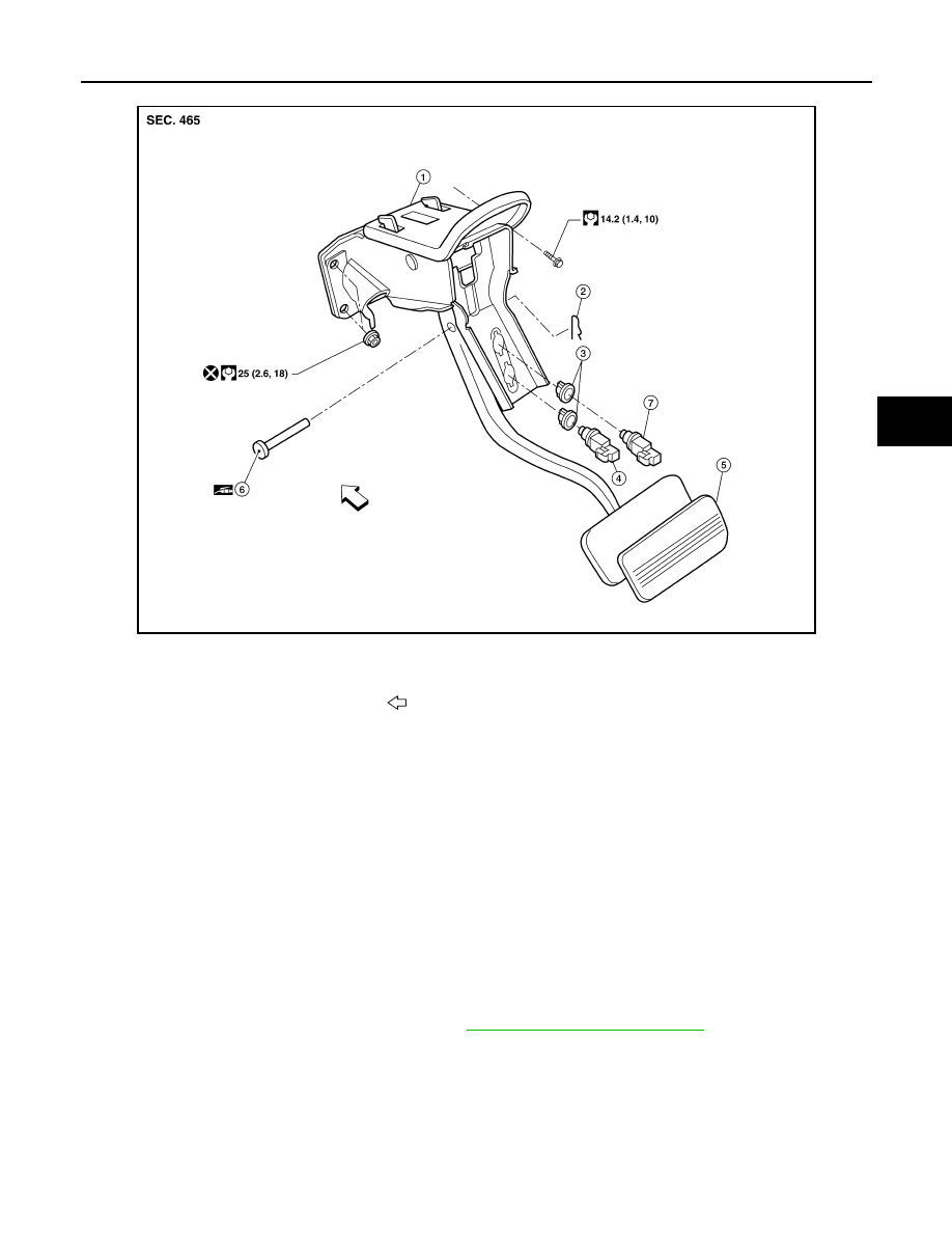
AWFIA0458GB

1.

Brake pedal assembly

2.

Snap pin

3.

Clip

4.

Stop lamp switch

5.

Pedal pad

6.

Clevis pin

7.

ASCD cancel switch

Front

August 2012

2012 Pathfinder

BR-24

< REMOVAL AND INSTALLATION >

BRAKE PEDAL

3. Disconnect the adjustable brake pedal cable from the adjustable

pedal.

• Release the two lock tabs, then pull the adjustable brake pedal

cable to disconnect it from the adjustable brake pedal.

4. Remove snap pin and clevis pin from the clevis of the brake booster.
5. Remove the brake pedal assembly bolt.
6. Remove the brake pedal assembly nuts, then remove the pedal assembly.

• Temporarily install the nuts by hand to support the booster.

CAUTION:

Do not reuse the nuts for installation.

Inspection After Removal

Check brake pedal for following items:

• Cracking or deformation of the clevis pin stopper (A)

• Clevis pin deformation

• Crack of any welded portion

• Brake pedal bent or deformed

Installation

Installation is in the reverse order of removal.

CAUTION:

Do not reuse the nuts for installation, discard and install with new lock nuts.

• Check the brake pedal for smooth operation. There should be no binding or sticking when applying or

releasing the brake pedal.

• Check the adjustable feature for smooth operation. There should be no binding or sticking when adjusting

the brake pedal forward and backward.

• After installing the brake pedal assembly, adjust it as necessary. Refer to 

BR-18, "Inspection and Adjustment

- Adjustable Pedal"

.

STANDARD BRAKE PEDAL

WARNING:

Do not deform the brake piping. 

CAUTION:

• Do not disassemble the brake pedal assembly.

• Avoid damage from dropping the brake pedal assembly during handling.

• Keep the brake pedal assembly away from water.

Removal

1. Remove the instrument lower panel LH. Refer to 

IP-15, "Removal and Installation"

.

2. Remove the stop lamp switch and ASCD cancel switch from the pedal assembly.
3. Remove snap pin and clevis pin from the clevis of the brake booster.
4. Remove the brake pedal assembly bolt.
5. Remove the brake pedal assembly nuts, then remove the pedal assembly.

• Temporarily install the nuts by hand to support the booster.

CAUTION:

LFIA0233E

PFIA0756J

August 2012

2012 Pathfinder

BRAKE PEDAL

BR-25

< REMOVAL AND INSTALLATION >

C

D

E

G

H

I

J

K

L

M

A

B

BR

N

O

P

Do not reuse the nuts for installation.

Inspection After Removal

Check brake pedal for following items:

• Cracking or deformation of clevis pin stopper (A)

• Clevis pin deformation

• Crack of any welded portion

• Brake pedal bent or deformed

Installation

Installation is in the reverse order of removal.

CAUTION:

Do not reuse the nuts for installation, discard and install with new lock nuts.

• Check the brake pedal for smooth operation. There should be no binding or sticking when applying or

releasing the brake pedal.

• After installing the brake pedal assembly, adjust it as necessary. Refer to 

BR-17, "Inspection and Adjustment

- Standard Pedal"

.

PFIA0756J

August 2012

2012 Pathfinder

BR-26

< REMOVAL AND INSTALLATION >

BRAKE TUBE AND HOSE

BRAKE TUBE AND HOSE

Hydraulic Circuit

INFOID:0000000007356620

Brake Tube and Hose Connections

AWFIA0411ZZ

1.

Actuator

2.

Master cylinder

3.

Brake booster

4.

Connector

A.

Union bolt
18.2 N·m (1.9 kg-m, 13 ft-lb)

B.

Flare nut M12
18.2 N·m (1.9 kg-m, 13 ft-lb)

C.

Flare nut M10
13.0 N·m (1.3 kg-m, 10 ft-lb)

August 2012

2012 Pathfinder

BRAKE TUBE AND HOSE

BR-27

< REMOVAL AND INSTALLATION >

C

D

E

G

H

I

J

K

L

M

A

B

BR

N

O

P

ABS Actuator and Electric Unit Brake Pipe Connections for VQ40DE

AWFIA0743GB

1.

From master cylinder secondary side
18.2 N·m (1.9 kg-m, 13 ft-lb)

2.

To rear right disc brake
13.0 N·m (1.3 kg-m, 10 ft-lb)

3.

To rear left disc brake
13.0 N·m (1.3 kg-m, 10 ft-lb)

4.

To front right disc brake
13.0 N·m (1.3 kg-m, 10 ft-lb)

5.

To front left disc brake
13.0 N·m (1.3 kg-m, 10 ft-lb)

6.

From master cylinder primary side
18.2 N·m (1.9 kg-m, 13 ft-lb)

7.

ABS actuator and electric unit (control 
unit)

8.

Harness connector

Front

August 2012

2012 Pathfinder

BR-28

< REMOVAL AND INSTALLATION >

BRAKE TUBE AND HOSE

ABS Actuator and Electric Unit Brake Pipe Connections for VK56DE

CAUTION:

• All hoses and piping (tubes) must be free from excessive bending, twisting and pulling.

• Make sure there is no interference with other parts when turning the steering wheel both clockwise

and counterclockwise.

• The brake piping is an important safety part. If a brake fluid leak is detected, always disassemble the

parts. Replace applicable part with a new one, if necessary.

• Be careful not to splash brake fluid on painted areas; it may cause paint damage. If brake fluid is

splashed on painted areas, wash it away with water immediately.

• Do not bend or twist brake hose sharply, or strongly pull it.

• When removing components, cover connections so that no dirt, dust, or other foreign matter gets in.

• Refill with new specified brake fluid. Refer to 

MA-18, "FOR USA AND CANADA : Fluids and Lubri-

cants"

 (United States and Canada), 

MA-20, "FOR MEXICO : Fluids and Lubricants"

 (Mexico).

• Do not reuse drained brake fluid.

Removal and Installation of Front Brake Piping and Brake Hose

INFOID:0000000007356621

NOTE:

When removing components such as hoses, tubes/lines, etc., cap or plug openings to prevent fluid from spill-

ing.

REMOVAL

1. Remove wheel and tire assembly.
2. Remove master cylinder reservoir cap.

WFIA0375E

1.

To rear left disc brake
13.0 N·m (1.3 kg-m, 10 ft-lb)

2.

To rear right disc brake
13.0 N·m (1.3 kg-m, 10 ft-lb)

3.

To front left disc brake
13.0 N·m (1.3 kg-m, 10 ft-lb)

4.

To front right disc brake
13.0 N·m (1.3 kg-m, 10 ft-lb)

5.

From the master cylinder secondary side
18.2 N·m (1.9 kg-m, 13 ft-lb)

6.

From the master cylinder primary side
18.2 N·m (1.9 kg-m, 13 ft-lb)

7.

ABS actuator and electric unit 
(control unit)

8.

Harness connector

August 2012

2012 Pathfinder

BRAKE TUBE AND HOSE

BR-29

< REMOVAL AND INSTALLATION >

C

D

E

G

H

I

J

K

L

M

A

B

BR

N

O

P

3. Remove brake tube from brake hose, using a suitable tool.
4. Remove lock plate and brake hose from bracket.

5. Remove union bolt and copper sealing washers, then remove

brake hose from caliper assembly.

CAUTION:

Do not reuse copper sealing washers.

INSTALLATION

1. Install brake hose by aligning with the protrusion on caliper

assembly, then install new copper sealing washers (1) and union

bolt (A). Tighten union bolt (A) to specified torque. Refer to 

BR-

26, "Hydraulic Circuit"

.

CAUTION:

Do not reuse copper sealing washers.

2. Insert brake hose end through bracket, then secure it to bracket

with lock plate.

3. Install brake tube to brake hose, then tighten flare nut to the

specified torque using a suitable tool. Refer to 

BR-26, "Hydraulic

Circuit"

.

4. Refill brake fluid and bleed brake system. Refer to 

BR-20, "Bleeding Brake System"

.

5. Install the wheel and tire assembly. Refer to 

WT-50, "Adjustment"

.

Removal and Installation of Rear Brake Piping and Brake Hose

INFOID:0000000007356622

NOTE:

When removing components such as hoses, tubes/lines, etc., cap or plug openings to prevent fluid from spill-

ing.

REMOVAL

1. Remove wheel and tire assembly.

LFIA0236E

LFIA0235E

AWFIA0795ZZ

LFIA0236E

August 2012

2012 Pathfinder

BR-30

< REMOVAL AND INSTALLATION >

BRAKE TUBE AND HOSE

2. Remove master cylinder reservoir cap.
3. Remove brake tube from brake hose, using a suitable tool.
4. Remove lock plate and brake hose from bracket.

5. Remove union bolt and copper sealing washers, then remove

brake hose from caliper assembly.

CAUTION:

Do not reuse copper sealing washers.

INSTALLATION

1. Install brake hose by aligning with the protrusion on caliper

assembly, then install new copper sealing washers (1) and union

bolt (A). Tighten union bolt (A) to specified torque. Refer to 

BR-

26, "Hydraulic Circuit"

.

CAUTION:

Do not reuse copper sealing washers.

2. Insert brake hose end through bracket, then secure it to bracket

with lock plate.

3. Install brake tube to brake hose, then tighten flare nut to the

specified torque using a suitable tool.

4. Refill brake fluid and bleed brake system. Refer to 

BR-20, "Bleeding Brake System"

.

5. Install the wheel and tire assembly. Refer to 

WT-50, "Adjustment"

.

Inspection After Installation

INFOID:0000000007356623

CAUTION:

Brake tubes and hoses are important safety parts. Always disassemble the parts and retighten their fit-

tings if a brake fluid leak is detected. Replace applicable part with a new one, if a damaged part is

detected.

LFIA0238E

LFIA0237E

AWFIA0795ZZ

LFIA0238E

August 2012

2012 Pathfinder


Content      ..     85      86      87      88     ..