Nissan Pathfinder (2012 year). Manual - part 31


  Index      Manuals     Nissan Pathfinder (2012 year) - Service and Repair Manual


Search            copyright infringement  


Content      ..     29      30      31      32     ..


Nissan Pathfinder (2012 year). Manual - part 31


AV-66

< DTC/CIRCUIT DIAGNOSIS >

[MID AUDIO]

POWER SUPPLY AND GROUND CIRCUIT

Are the continuity results as specified?

YES

>> Inspection End.

NO

>> Repair AV control unit ground.

DISPLAY UNIT
DISPLAY UNIT : Diagnosis Procedure

INFOID:0000000007347631

Regarding Wiring Diagram information, refer to 

AV-95, "Wiring Diagram"

.

1.

CHECK POWER SUPPLY CIRCUIT

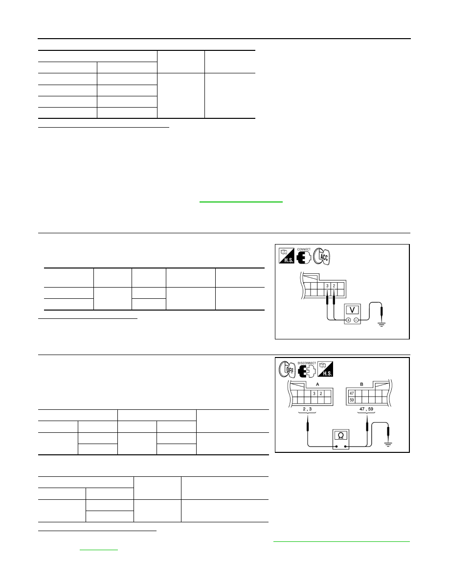
1. Turn ignition switch to ACC.

2. Check voltage between display unit harness connector M93 and

ground.

Does specified voltage exist?

YES

>> GO TO 3

NO

>> GO TO 2

2.

CHECK POWER SUPPLY CIRCUIT

1. Turn ignition switch OFF.

2. Disconnect the display unit connector M93 and the AV control

unit connector M133.

3. Check continuity between the display unit harness connector

M93 (A) and the AV control unit connector M133 (B).

4. Check continuity between the display unit harness connector M93 (A) and ground.

Are continuity results as specified?

YES

>> Check AV control unit power and ground supply. Refer to 

AV-65, "AV CONTROL UNIT : Diagnosis

Procedure"

.

NO

>> Repair harness or connector.

(+)

(-)

Continuity

Connector

Terminal

M131

20

Ground

Yes

M133

54

M134

68

M135

85

Signal name

Connector

Terminal

Ignition switch 

position

Value (Approx.)

Inverter VCC

M93

2

ACC

9V

Signal VCC

3

ALNIA0317GB

A

B

Continuity

Connector

Terminal

Connector

Terminal

M93

2

M133

59

Yes

3

47

A

Continuity

Connector

Terminal

M93

2

Ground

No

3

ALNIA0318GB

August 2012

2012 Pathfinder

AV

POWER SUPPLY AND GROUND CIRCUIT

AV-67

< DTC/CIRCUIT DIAGNOSIS >

[MID AUDIO]

C

D

E

F

G

H

I

J

K

L

M

B

A

O

P

3.

CHECK GROUND CIRCUIT

1. Turn ignition switch OFF.

2. Disconnect display unit connector.

3. Check continuity between display unit harness connector and

ground.

Does continuity exist?

YES

>> Inspection End.

NO

>> Repair harness or connector.

A/C AND AV SWITCH ASSEMBLY
A/C AND AV SWITCH ASSEMBLY : Diagnosis Procedure

INFOID:0000000007347632

Regarding Wiring Diagram information, refer to 

AV-95, "Wiring Diagram"

.

1.

CHECK FUSE

Check that the fuse of the AC and AV switch assembly is not blown.

Is the fuse OK?

YES

>> GO TO 2

NO

>> If fuse is blown, be sure to eliminate cause of malfunction before installing new fuse.

2.

POWER SUPPLY CIRCUIT CHECK

1. Disconnect A/C and AV switch assembly connector M98. 

2. Check voltage between the A/C and AV switch assembly con-

nector M98 and ground.

Are the voltage results as specified?

YES

>> GO TO 3

NO

>> • Check connector housings for disconnected or loose

terminals.

• Repair harness or connector.

3.

GROUND CIRCUIT CHECK

Connector

Terminal

Continuity

M93

1

Ground

Yes

ALNIA0319GB

Unit

Terminal

Signal name

Fuse No.

A/C and AV switch assembly

2

Ignition switch ACC or ON

4

(+)

(-)

OFF

ACC

ON

Connector

Terminal

M98

2

Ground

0V

Battery 
voltage

Battery 
voltage

ALNIA0315GB

August 2012

2012 Pathfinder

AV-68

< DTC/CIRCUIT DIAGNOSIS >

[MID AUDIO]

POWER SUPPLY AND GROUND CIRCUIT

1. Turn ignition switch OFF.

2. Check continuity between A/C and AV switch assembly harness

connector M98 and ground.

Are the continuity results as specified?

YES

>> Inspection End.

NO

>> Repair harness or ground.

REAR VIEW CAMERA
REAR VIEW CAMERA : Diagnosis Procedure

INFOID:0000000007347633

Regarding Wiring Diagram information, refer to 

AV-95, "Wiring Diagram"

.

1.

CHECK POWER SUPPLY CIRCUIT (REAR VIEW CAMERA SIDE)

NOTE:

Apply parking brakes before proceeding.

1. Turn ignition switch ON.

2. Shift transmission into reverse.

3. Check voltage between rear view camera harness connector D551 terminal 2 and ground.

Is voltage reading approximately 12 volts?

YES

>> GO TO 4.

NO

>> GO TO 2.

2.

CHECK POWER SUPPLY CIRCUIT (CONTINUITY)

1. Turn ignition switch OFF.

2. Disconnect rear view camera and AV control unit connectors.

3. Check continuity between rear view camera harness connector D551 terminal 2 and AV control unit har-

ness connector M134 terminal 105. 

4. Check continuity between rear view camera harness connector D551 terminal 2 and ground. 

Are continuity test results as specified?

YES

>> GO TO 3.

NO

>> Repair harness or connector.

3.

CHECK REVERSE POSITION INPUT SIGNAL

1. Turn ignition switch ON.

2. Shift transmission into reverse.

3. Check voltage between AV control unit harness connector M134 terminal 105 and ground.

Connector

Terminal

Continuity

M98

1

Ground

Yes

ALNIA0316GB

(+)

(-)

Transmission 

position

Value (Approx.)

Connector

Terminal

D551

2

Ground

Reverse

12V

Connector

Terminal

Connector

Terminal

Continuity

D551

2

M134

105

Yes

Connector

Terminal

Continuity

D551

2

Ground

No

August 2012

2012 Pathfinder

AV

POWER SUPPLY AND GROUND CIRCUIT

AV-69

< DTC/CIRCUIT DIAGNOSIS >

[MID AUDIO]

C

D

E

F

G

H

I

J

K

L

M

B

A

O

P

Is voltage reading approximately 12 volts?

YES

>> Replace AV control unit. Refer to 

AV-114, "Removal and Installation"

.

NO

>> Check harness for open or short between AV control unit and back-up lamp relay.

4.

CHECK GROUND CIRCUIT

1. Turn ignition switch OFF.

2. Disconnect rear view camera harness connector.

3. Check continuity between rear view camera harness connector D551 terminal 1 and ground. 

Does continuity exist?

YES

>> Inspection End.

NO

>> Repair harness or connector.

(+)

(-)

Transmission 

position

Value (Approx.)

Connector

Terminal

M134

105

Ground

Reverse

12V

Connector

Terminal

Continuity

D551

1

Ground

Yes

August 2012

2012 Pathfinder

AV-70

< DTC/CIRCUIT DIAGNOSIS >

[MID AUDIO]

RGB (R: RED) SIGNAL CIRCUIT

RGB (R: RED) SIGNAL CIRCUIT

Description

INFOID:0000000007347634

Transmit the image displayed with AV control unit with RGB signal to the display unit.

Diagnosis Procedure

INFOID:0000000007347635

Regarding Wiring Diagram information, refer to 

AV-95, "Wiring Diagram"

.

1.

CHECK CONTINUITY RGB (R: RED) SIGNAL CIRCUIT

1. Turn ignition switch OFF.

2. Disconnect display unit connector M93 and AV control unit con-

nector M133.

3. Check continuity between display unit harness connector M93

(A) terminal 17 and AV control unit harness connector M133 (B)

terminal 40.

4. Check continuity between display unit harness connector M93

(A) terminal 17 and ground.

Are the continuity results as specified?

YES

>> GO TO 2

NO

>> Repair harness or connector.

2.

CHECK RGB (R: RED) SIGNAL

1. Connect display unit connector M93 and AV control unit connec-

tor M133.

2. Turn ignition switch ON.

3. Check signal between display unit harness connector M93 ter-

minal 17 and ground.

Are the voltage readings as specified?

YES

>> Replace display unit. Refer to 

AV-116, "Removal and Installation"

.

NO

>> Replace AV control unit. Refer to 

AV-114, "Removal and Installation"

.

A

B

Continuity

Connector

Terminal

Connector

Terminal

M93

17

M133

40

Yes

A

Continuity

Connector

Terminal

M93

17

Ground

No

ALNIA0382GB

(+)

(-)

Condition

Reference signal

Connector

Terminal

M93

17

Ground

Receive 
audio sig-
nal

ALNIA0383GB

SKIB2238J

August 2012

2012 Pathfinder

AV

RGB (G: GREEN) SIGNAL CIRCUIT

AV-71

< DTC/CIRCUIT DIAGNOSIS >

[MID AUDIO]

C

D

E

F

G

H

I

J

K

L

M

B

A

O

P

RGB (G: GREEN) SIGNAL CIRCUIT

Description

INFOID:0000000007347636

Transmit the image displayed with AV control unit with RGB signal to the display unit.

Diagnosis Procedure

INFOID:0000000007347637

Regarding Wiring Diagram information, refer to 

AV-95, "Wiring Diagram"

.

1.

CHECK CONTINUITY RGB (G: GREEN) SIGNAL CIRCUIT

1. Turn ignition switch OFF.

2. Disconnect display unit connector M93 and AV control unit con-

nector M133.

3. Check continuity between display unit harness connector M93

(A) terminal 6 and AV control unit harness connector M133 (B)

terminal 39.

4. Check continuity between display unit harness connector M93

(A) terminal 6 and ground.

Are the continuity results as specified?

YES

>> GO TO 2

NO

>> Repair harness or connector.

2.

CHECK RGB (G: GREEN) SIGNAL

1. Connect display unit connector M93 and AV control unit connec-

tor M133.

2. Turn ignition switch ON.

3. Check signal between display unit harness connector M93 ter-

minal 6 and ground.

Are voltage readings as specified?

YES

>> Replace display unit. Refer to 

AV-116, "Removal and Installation"

.

NO

>> Replace AV control unit. Refer to 

AV-114, "Removal and Installation"

.

A

B

Continuity

Connector

Terminal

Connector

Terminal

M93

6

M133

39

Yes

A

Continuity

Connector

Terminal

M93

6

Ground

No

ALNIA0384GB

(+)

(-)

Condition

Reference signal

Connector

Terminal

M93

6

Ground

Receive 
audio sig-
nal

ALNIA0385GB

SKIB2236J

August 2012

2012 Pathfinder

AV-72

< DTC/CIRCUIT DIAGNOSIS >

[MID AUDIO]

RGB (B: BLUE) SIGNAL CIRCUIT

RGB (B: BLUE) SIGNAL CIRCUIT

Description

INFOID:0000000007347638

Transmit the image displayed with AV control unit with RGB signal to the display unit.

Diagnosis Procedure

INFOID:0000000007347639

Regarding Wiring Diagram information, refer to 

AV-95, "Wiring Diagram"

.

1.

CHECK CONTINUITY RGB (B: BLUE) SIGNAL CIRCUIT

1. Turn ignition switch OFF.

2. Disconnect display unit connector M93 and AV control unit con-

nector M133.

3. Check continuity between display unit harness connector M93

(A) terminal 18 and AV control unit harness connector M133 (B)

terminal 38.

4. Check continuity between display unit harness connector M93

(A) terminal 18 and ground.

Are continuity results as specified?

YES

>> GO TO 2

NO

>> Repair harness or connector.

2.

CHECK RGB (B: BLUE) SIGNAL

1. Connect display unit connector M93 and AV control unit connec-

tor M133.

2. Turn ignition switch ON.

3. Check signal between display unit harness connector M93 ter-

minal 18 and ground.

Are voltage readings as specified?

YES

>> Replace display unit. Refer to 

AV-116, "Removal and Installation"

.

NO

>> Replace AV control unit. Refer to 

AV-114, "Removal and Installation"

.

A

B

Continuity

Connector

Terminal

Connector

Terminal

M93

18

M133

38

Yes

A

Continuity

Connector

Terminal

M93

18

Ground

No

ALNIA0386GB

(+)

(-)

Condition

Reference signal

Connector

Terminal

M93

18

Ground

Receive 
audio sig-
nal

ALNIA0387GB

SKIB2237J

August 2012

2012 Pathfinder

AV

RGB SYNCHRONIZING SIGNAL CIRCUIT

AV-73

< DTC/CIRCUIT DIAGNOSIS >

[MID AUDIO]

C

D

E

F

G

H

I

J

K

L

M

B

A

O

P

RGB SYNCHRONIZING SIGNAL CIRCUIT

Description

INFOID:0000000007347640

Transmit the RGB synchronizing signal to the display unit so as to synchronize the RGB image displayed with

AV control unit.

Diagnosis Procedure

INFOID:0000000007347641

Regarding Wiring Diagram information, refer to 

AV-95, "Wiring Diagram"

.

1.

CHECK CONTINUITY RGB SYNCHRONIZING SIGNAL CIRCUIT

1. Turn ignition switch OFF.

2. Disconnect display unit connector M93 and AV control unit con-

nector M133.

3. Check continuity between display unit harness connector M93

(A) terminal 19 and AV control unit harness connector M133 (B)

terminal 41.

4. Check continuity between display unit harness connector M93

(A) terminal 19 and ground.

Are continuity results as specified?

YES

>> GO TO 2

NO

>> Repair harness or connector.

2.

CHECK RGB SYNCHRONIZING SIGNAL

1. Connect display unit connector M93 and AV control unit connec-

tor M133.

2. Turn ignition switch ON.

3. Check signal between display unit harness connector M93 ter-

minal 19 and ground.

Are voltage readings as specified?

YES

>> Replace display unit. Refer to 

AV-116, "Removal and Installation"

.

NO

>> Replace AV control unit. Refer to 

AV-114, "Removal and Installation"

.

A

B

Continuity

Connector

Terminal

Connector

Terminal

M93

19

M133

41

Yes

A

Continuity

Connector

Terminal

M93

19

Ground

No

ALNIA0388GB

(+)

(-)

Condition

Reference signal

Connector

Terminal

M93

19

Ground

Receive 
audio sig-
nal

ALNIA0389GB

SKIB3603E

August 2012

2012 Pathfinder


Content      ..     29      30      31      32     ..