Nissan Pathfinder (2011 year). Manual - part 440


  Index      Manuals     Nissan Pathfinder (2011 year) - Service and Repair Manual


Search            copyright infringement  


Content      ..     438      439      440      441     ..


Nissan Pathfinder (2011 year). Manual - part 440


COMPRESSOR

HA-41

< REMOVAL AND INSTALLATION >

C

D

E

F

G

H

J

K

L

M

A

B

HA

N

O

P

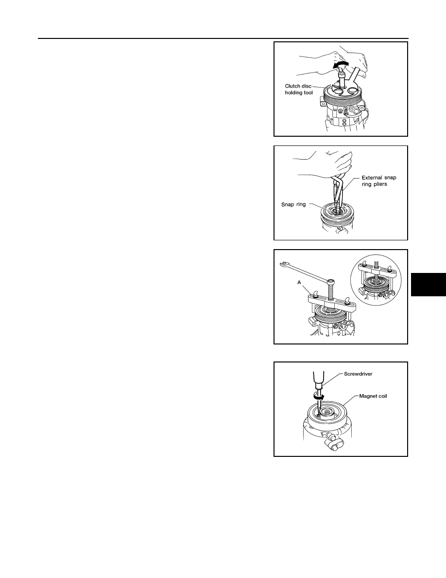
3. Remove the center bolt while holding the clutch disc stationary

using Tool as shown.

4. Remove the clutch disc and shims.

CAUTION:

Retain shims for installation.

5. Remove the snap ring using a suitable tool.

6. Remove the pulley using a suitable tool (A).

CAUTION:

To prevent deformation of the pulley groove, the puller

claws should be hooked under the pulley groove and not

into the pulley groove.

7. Remove the magnet coil.

• For the VK56DE engine, using a suitable tool remove the

three magnet coil screws and remove the magnet coil.

Tool number

: J-44614

WHA228

RHA072C

AWIIA1285ZZ

WHA212

2011 Pathfinder

HA-42

< REMOVAL AND INSTALLATION >

COMPRESSOR

• For the VQ40DE engine, remove the magnet coil snap ring (A)

using a suitable tool and remove the magnet coil (1).

INSPECTION

Clutch Disc

If the contact surface shows signs of damage due to excessive heat, replace clutch disc and pulley.

Pulley

Check the appearance of the pulley assembly. If contact surface of pulley shows signs of excessive grooving,

replace clutch disc and pulley. The contact surfaces of the pulley assembly should be cleaned with a suitable

solvent before reinstallation.

Coil

Check magnet coil for loose connections or any cracked insulation. Replace as necessary.

INSTALLATION

1. Install the magnet coil.

• For the VK56DE engine, position the magnet coil and, using a

suitable tool, install the three magnet coil screws.

• For the VQ40DE engine, position the magnet coil (1) and

install the magnet coil snap ring (A) using a suitable tool.

CAUTION:

Be sure to align the magnet coil pin with the hole in the

compressor front head.

ALIIA0379ZZ

WHA212

ALIIA0379ZZ

2011 Pathfinder

COMPRESSOR

HA-43

< REMOVAL AND INSTALLATION >

C

D

E

F

G

H

J

K

L

M

A

B

HA

N

O

P

2. Install the pulley assembly using Tool and a wrench, then install

the snap ring using a suitable tool.

3. Install the clutch disc on the compressor shaft, together with the

original shim(s) using a suitable tool. Press the clutch disc in by

hand.

4. Install the clutch pulley bolt while using Tool to prevent the clutch

disc from turning and tighten the bolt to specification.

CAUTION:

After tightening the clutch pulley bolt, check that the clutch

pulley rotates smoothly.

5. Check the pulley clearance all the way around the clutch disc as

shown.

6. If the specified clearance is not obtained, replace the adjusting

spacer to readjust.

Tool number

: — (J-38873-A)

WJIA1016E

WHA184

Tool number

: J-44614

WHA229

Clutch disc-to-pulley clearance

: 0.3 - 0.6 mm 
(0.012 - 0.024 in)

WHA194

2011 Pathfinder

HA-44

< REMOVAL AND INSTALLATION >

COMPRESSOR

7. For VK56DE, install the compressor. Refer to 

HA-38, "Removal and Installation for Compressor"

.

8. For VQ40DE, install the engine cooling fan. Refer to 

CO-21, "Removal and Installation (Crankshaft driven

type)"

.

BREAK-IN OPERATION

When replacing compressor clutch assembly, always conduct the break-in operation. This is done by engag-

ing and disengaging the clutch about 30 times. Break-in operation raises the level of transmitted torque.

2011 Pathfinder

HIGH-PRESSURE FLEXIBLE HOSE

HA-45

< REMOVAL AND INSTALLATION >

C

D

E

F

G

H

J

K

L

M

A

B

HA

N

O

P

HIGH-PRESSURE FLEXIBLE HOSE

Removal and Installation for Front High-pressure Flexible A/C Hose

INFOID:0000000006243600

REMOVAL

1. Remove the front left wheel and tire assembly. Refer to 

WT-50, "Adjustment"

.

2. Remove the front left fender protector. Refer to 

EXT-25, "Removal and Installation of Front Fender Protec-

tor"

.

3. Discharge the refrigerant. Refer to 

HA-36, "HFC-134a (R-134a) Service Procedure"

.

4. Remove the front high-pressure flexible A/C hose. Refer to 

HA-34, "Component"

.

CAUTION:

Cap or wrap the joint of the pipe with suitable material such as vinyl tape to avoid the entry of air. 

INSTALLATION

Installation is in the reverse order of removal.

Refer to 

HA-34, "Component"

.

CAUTION:

• Do not reuse O-rings.

• Apply A/C oil to the O-ring of the front high-pressure flexible A/C hose for installation.

• After charging refrigerant, check for leaks.

2011 Pathfinder

HA-46

< REMOVAL AND INSTALLATION >

HIGH-PRESSURE PIPE

HIGH-PRESSURE PIPE

Removal and Installation for Front High-pressure A/C Pipe

INFOID:0000000006243601

REMOVAL

1. Remove the front right wheel and tire assembly. Refer to 

WT-50, "Adjustment"

.

2. Remove the front right fender protector. Refer to 

EXT-25, "Removal and Installation of Front Fender Pro-

tector"

.

3. Discharge the refrigerant. Refer to 

HA-36, "HFC-134a (R-134a) Service Procedure"

.

4. Remove the front low pressure A/C pipe. Refer to 

HA-50, "Removal and Installation for Front Low-Pres-

sure A/C Pipe"

.

5. Remove the front high-pressure A/C pipe. Refer to 

HA-34, "Component"

.

CAUTION:

Cap or wrap the joint of the pipe with suitable material such as vinyl tape to avoid the entry of air. 

INSTALLATION

Installation is in the reverse order of removal.

Refer to 

HA-34, "Component"

.

CAUTION:

• Do not reuse O-rings.

• Apply A/C oil to the O-ring of the front high-pressure A/C pipe for installation.

• After charging refrigerant, check for leaks.

Removal and Installation for Rear High- and Low-Pressure A/C Pipes

INFOID:0000000006243602

REMOVAL

1. Discharge the refrigerant. Refer to 

HA-36, "HFC-134a (R-134a) Service Procedure"

.

2. Remove the luggage side lower finisher RH. Refer to 

INT-24, "Component"

.

3. Remove the rear high- and low-pressure A/C pipes. Refer to 

HA-34, "Component"

.

CAUTION:

Cap or wrap the joint of the pipe with suitable material such as vinyl tape to avoid the entry of air. 

INSTALLATION

Installation is in the reverse order of removal.

Refer to 

HA-34, "Component"

.

CAUTION:

• Do not reuse O-rings.

• Apply A/C oil to the O-ring of the rear high-and low-pressure A/C pipes for installation.

• After charging refrigerant, check for leaks.

Removal and Installation for Underfloor Rear High- and Low-Pressure A/C and Heater 
Core Pipes

INFOID:0000000006243603

REMOVAL

1. Release the fuel pressure. Refer to 

EC-484, "Fuel Pressure Check"

 (VQ40DE), 

EC-938, "Fuel Pressure

Check"

 (VK56DE).

2. Drain the engine coolant. Refer to 

CO-13, "Changing Engine Coolant"

 (VQ40DE)

CO-44, "Changing

Engine Coolant"

 (VK56DE).

3. Disconnect the negative battery terminal.
4. Discharge the refrigerant. Refer to 

HA-36, "HFC-134a (R-134a) Service Procedure"

.

5. Remove the front and rear RH wheels and tires. Refer to 

WT-50, "Adjustment"

.

6. Remove the rear bumper. Refer to 

EXT-18, "Removal and Installation"

.

7. Disconnect the fuel filler pipe and vent pipe from the lower fuel filler hose and fuel tank.
8. Remove the front fender protector. Refer to 

EXT-25, "Removal and Installation of Front Fender Protector"

.

9. Disconnect the chassis harness connector.
10. Disconnect the fuel feed hose quick connectors. Disconnect the quick connectors as follows:

2011 Pathfinder

HIGH-PRESSURE PIPE

HA-47

< REMOVAL AND INSTALLATION >

C

D

E

F

G

H

J

K

L

M

A

B

HA

N

O

P

• Hold the sides of the connector, push in the tabs and pull out the tube.

• If the connector and the tube are stuck together, push and pull several times until they start to move.

Then disconnect them by pulling.

CAUTION:

• The quick connector can be disconnected when the tabs

are completely depressed. Do not twist the quick connec-

tor more than necessary.

• Do not use any tools to disconnect the quick connector.

• Keep the resin tube away from heat. Be especially careful

when welding near the tube.

• Prevent any acid liquids such as battery electrolyte, from

getting on the resin tube.

• Do not bend or twist the resin tube during connection. 

• Do not remove the remaining retainer on the hard tube (or

the equivalent) except when the resin tube or the retainer

is replaced.

• When the resin tube or hard tube, or the equivalent, is 

replaced, also replace the retainer with a new one (semi-

transparent colored retainer).

• To keep the quick connector clean and to avoid damage

and contamination from foreign materials, cover the quick

connector with plastic bags or suitable material as shown.      

11. Disconnect the frame mounted brake tubes from the brake system. Refer to 

BR-28, "Removal and Instal-

lation of Front Brake Piping and Brake Hose"

.

12. Remove the upper radiator mounting plates. Refer to 

CO-18, "Exploded View"

 (VQ40DE), 

CO-49,

"Exploded View"

 (VK56DE).

13. Disconnect the A/C lines ground strap.
14. Disconnect the exhaust system ground strap. Refer to 

EX-7, "Removal and Installation"

.

15. Disconnect each end of the underfloor rear high- and low-pressure A/C and heater core pipes. Refer to

HA-34, "Component"

.

CAUTION:

Cap or wrap the joint of the pipes with suitable material such as vinyl tape to avoid the entry of air. 

16. Remove the front floor heat shield.
17. Remove the heater pipe heat shield.
18. Disconnect the steering column from the power steering gear. Refer to 

ST-19, "Removal and Installation"

.

19. Set four suitable jacks at the body mount points to support the vehicle body when it is separated from the

frame.

20. Remove the body mount bolts. Refer to 

BRM-10, "Body Mounting"

.

PBIC1268E

PBIC0163E

2011 Pathfinder

HA-48

< REMOVAL AND INSTALLATION >

HIGH-PRESSURE PIPE

21. Use the vehicle hoist to lower the frame from the body [approximately 457 mm (18 in)] until there is suffi-

cient clearance for the underfloor rear high- and low-pressure A/C and heater core pipes from the body.

22. Remove the underfloor rear high- and low-pressure A/C and heater core pipes.

INSTALLATION

Installation is in the reverse order of removal.

CAUTION:

• Do not reuse O-rings.

• Apply A/C oil to the O-ring of the underfloor rear high-and low-pressure A/C and heater core pipes

for installation.

• After charging refrigerant, check for leaks.

• Bleed the brake system. Refer to 

BR-20, "Bleeding Brake System"

.

2011 Pathfinder


Content      ..     438      439      440      441     ..