Nissan Pathfinder (2011 year). Manual - part 422


  Index      Manuals     Nissan Pathfinder (2011 year) - Service and Repair Manual


Search            copyright infringement  


Content      ..     420      421      422      423     ..


Nissan Pathfinder (2011 year). Manual - part 422


FUEL LEVEL SENSOR UNIT, FUEL FILTER AND FUEL PUMP ASSEMBLY

FL-15

< REMOVAL AND INSTALLATION >

C

D

E

F

G

H

I

J

K

L

M

A

FL

N

P

O

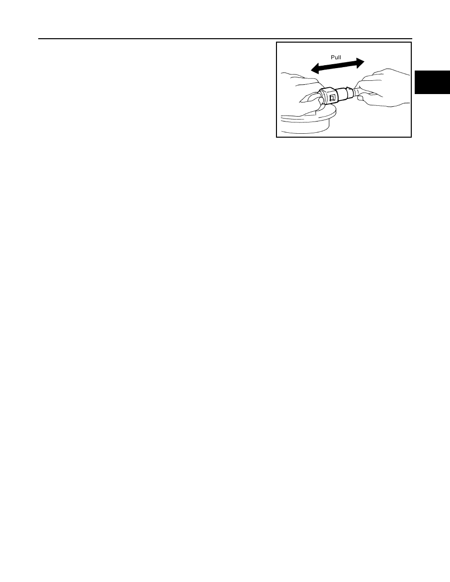
- After connecting the quick connector, make sure that the connec-

tion is secure by checking as follows:

- Pull the tube and the connector to make sure they are securely

connected.

- Visually inspect the connector to make sure the two retainer tabs

are securely connected.

INSPECTION AFTER INSTALLATION

1. Turn the ignition switch ON but do not start engine, then check the fuel pipe and hose connections for

leaks while applying fuel pressure.

2. Start the engine and rev it above idle, then check that there are no fuel leaks at any of the fuel pipe and

hose connections.

PBIC1653E

2011 Pathfinder

FL-16

< REMOVAL AND INSTALLATION >

EVAP CANISTER

EVAP CANISTER

Component Inspection

INFOID:0000000006824009

EVAP CANISTER

Check EVAP canister as per the following:
1. Block port (B).
2. Blow air into port (A) and check that it flows freely out of port (C).
3. Release blocked port (B).
4. Apply vacuum pressure to port (B) and check that vacuum pres-

sure exists at the ports (A) and (C).

5. Block port (A) and (B).
6. Apply pressure to port (C) and check that there is no leakage.

Removal and Installation

INFOID:0000000006824011

EVAP CANISTER

Removal

1. Disconnect the EVAP control pressure sensor connector.
2. Remove the EVAP control pressure sensor and O-ring.
3. Disconnect the EVAP canister purge hose.
4. Disconnect the EVAP vent control valve connector.
5. Remove the EVAP canister retaining bolt.
6. Disconnect the fuel tank EVAP breather hose.
7. Disconnect the EVAP vent control valve hose.
8. Remove the EVAP canister.
9. Remove the EVAP vent control valve and O-ring, if necessary.

Installation

Installation is in the reverse order of removal.

CAUTION:

Do not reuse O-ring.

PBIB2568E

1.

EVAP canister vent control valve

2.

EVAP canister system pressure sensor 3.

O-ring

4.

EVAP canister

ALBIA0674GB

2011 Pathfinder

EVAP CANISTER

FL-17

< REMOVAL AND INSTALLATION >

C

D

E

F

G

H

I

J

K

L

M

A

FL

N

P

O

EVAP CANISTER CONTROL PRESSURE SENSOR

Removal

1. Disconnect the EVAP control pressure sensor connector.
2. Remove the EVAP canister control pressure sensor and O-ring.

Installation

Installation is in the reverse order of removal.

CAUTION:

Do not reuse O-ring.

EVAP CANISTER VENT CONTROL VALVE

Removal

1. Disconnect the EVAP control pressure sensor connector.
2. Disconnect the EVAP canister purge hose.
3. Remove the EVAP canister retaining bolt.
4. Disconnect the fuel tank EVAP breather hose.
5. Disconnect the EVAP vent control valve connector.
6. Disconnect the EVAP vent control valve hose.
7. Reposition the EVAP canister.
8. Turn EVAP canister vent control valve counterclockwise.
9. Remove the EVAP canister vent control valve and O-ring.

Installation

Installation is in the reverse order of removal.

CAUTION:

Do not reuse O-ring.

BBIA0567E

2011 Pathfinder

FL-18

< UNIT DISASSEMBLY AND ASSEMBLY >

FUEL LEVEL SENSOR UNIT, FUEL FILTER AND FUEL PUMP ASSEMBLY

UNIT DISASSEMBLY AND ASSEMBLY

FUEL LEVEL SENSOR UNIT, FUEL FILTER AND FUEL PUMP ASSEMBLY

Disassembly and Assembly

INFOID:0000000006246187

Fuel Level Sensor Unit Assembly

Disassembly

1. Disconnect the harness connector.
2. Remove the fuel tank temperature sensor.
3. Remove the fuel level sensor unit assembly.

Assembly

Assembly is the reverse order of disassembly.

WAIA0114E

1.

Harness connector

2.

Fuel tank temperature sensor

3.

Fuel level sensor unit assembly

2011 Pathfinder

SERVICE DATA AND SPECIFICATIONS (SDS)

FL-19

< SERVICE DATA AND SPECIFICATIONS (SDS) 

C

D

E

F

G

H

I

J

K

L

M

A

FL

N

P

O

SERVICE DATA AND SPECIFICATIONS (SDS)

SERVICE DATA AND SPECIFICATIONS (SDS)

Standard and Limit

INFOID:0000000006246188

Fuel tank capacity

80   (21 1/8 US gal, 17 5/8 Imp gal)

2011 Pathfinder

FSU-1

SUSPENSION

C

D

F

G

H

I

J

K

L

M

SECTION 

FSU

A

B

FSU

N

O

P

CONTENTS

FRONT SUSPENSION

PRECAUTION ...............................................

2

PRECAUTIONS ...................................................

2

Precaution for Supplemental Restraint System 
(SRS) "AIR BAG" and "SEAT BELT PRE-TEN-
SIONER" .................................................................
..

2

Precaution Necessary for Steering Wheel Rota-
tion After Battery Disconnect ...................................
..

2

Precaution for Front Suspension ...............................

3

PREPARATION ............................................

4

PREPARATION ...................................................

4

Special Service Tool  .................................................

4

Commercial Service Tool  ..........................................

4

SYMPTOM DIAGNOSIS  ...............................

6

NOISE, VIBRATION, AND HARSHNESS 
(NVH) TROUBLESHOOTING  .............................

6

NVH Troubleshooting Chart  ......................................

6

PERIODIC MAINTENANCE ..........................

7

ON-VEHICLE SERVICE  ......................................

7

Front Suspension Parts .............................................

7

Front Wheel Alignment ..............................................

7

UPPER BALL JOINT AND LOWER BALL 
JOINT .................................................................

11

Inspection ................................................................

11

KNUCKLE ..........................................................

13

On-Vehicle Inspection and Service  .........................

13

REMOVAL AND INSTALLATION ...............

14

FRONT SUSPENSION ASSEMBLY  ..................

14

Component ..............................................................

14

UNIT REMOVAL AND INSTALLATION ......

15

COIL SPRING AND SHOCK ABSORBER  .......

15

Removal and Installation  .........................................

15

Disposal ...................................................................

15

STABILIZER BAR .............................................

16

Removal and Installation  .........................................

16

UPPER LINK  .....................................................

17

Removal and Installation  .........................................

17

LOWER LINK  ....................................................

18

Removal and Installation  .........................................

18

UPPER BALL JOINT AND LOWER BALL 
JOINT ................................................................

19

Removal and Installation  .........................................

19

KNUCKLE .........................................................

20

Removal and Installation  .........................................

20

UNIT DISASSEMBLY AND ASSEMBLY  ....

23

COIL SPRING AND SHOCK ABSORBER  .......

23

Disassembly and Assembly .....................................

23

SERVICE DATA AND SPECIFICATIONS 
(SDS) ............................................................

25

SERVICE DATA AND SPECIFICATIONS 
(SDS) .................................................................

25

General Specification (Front) ...................................

25

Spring Free Height  ..................................................

25

Wheel Alignment (Unladen*1)  .................................

25

Ball Joint  ..................................................................

26

Wheelarch Height (Unladen*1) ................................

26

2011 Pathfinder

FSU-2

< PRECAUTION >

PRECAUTIONS

PRECAUTION

PRECAUTIONS

Precaution for Supplemental Restraint System (SRS) "AIR BAG" and "SEAT BELT 
PRE-TENSIONER"

INFOID:0000000006245776

The Supplemental Restraint System such as “AIR BAG” and “SEAT BELT PRE-TENSIONER”, used along

with a front seat belt, helps to reduce the risk or severity of injury to the driver and front passenger for certain

types of collision. This system includes seat belt switch inputs and dual stage front air bag modules. The SRS

system uses the seat belt switches to determine the front air bag deployment, and may only deploy one front

air bag, depending on the severity of a collision and whether the front occupants are belted or unbelted.

Information necessary to service the system safely is included in the SR and SB section of this Service Man-

ual.

WARNING:

• To avoid rendering the SRS inoperative, which could increase the risk of personal injury or death in

the event of a collision which would result in air bag inflation, all maintenance must be performed by

an authorized NISSAN/INFINITI dealer.

• Improper maintenance, including incorrect removal and installation of the SRS, can lead to personal

injury caused by unintentional activation of the system. For removal of Spiral Cable and Air Bag

Module, see the SR section.

• Do not use electrical test equipment on any circuit related to the SRS unless instructed to in this

Service Manual. SRS wiring harnesses can be identified by yellow and/or orange harnesses or har-

ness connectors.

PRECAUTIONS WHEN USING POWER TOOLS (AIR OR ELECTRIC) AND HAMMERS

WARNING:

• When working near the Airbag Diagnosis Sensor Unit or other Airbag System sensors with the Igni-

tion ON or engine running, DO NOT use air or electric power tools or strike near the sensor(s) with a

hammer. Heavy vibration could activate the sensor(s) and deploy the air bag(s), possibly causing

serious injury.

• When using air or electric power tools or hammers, always switch the Ignition OFF, disconnect the

battery, and wait at least 3 minutes before performing any service.

Precaution Necessary for Steering Wheel Rotation After Battery Disconnect

INFOID:0000000006245777

NOTE:

• This Procedure is applied only to models with Intelligent Key system and NATS (NISSAN ANTI-THEFT SYS-

TEM).

• Remove and install all control units after disconnecting both battery cables with the ignition knob in the

LOCK

 position.

• Always use CONSULT-III to perform self-diagnosis as a part of each function inspection after finishing work.

If DTC is detected, perform trouble diagnosis according to self-diagnostic results.

For models equipped with the Intelligent Key system and NATS, an electrically controlled steering lock mech-

anism is adopted on the key cylinder.

For this reason, if the battery is disconnected or if the battery is discharged, the steering wheel will lock and

steering wheel rotation will become impossible.

If steering wheel rotation is required when battery power is interrupted, follow the procedure below before

starting the repair operation.

OPERATION PROCEDURE

1. Connect both battery cables.

NOTE:

Supply power using jumper cables if battery is discharged.

2. Use the Intelligent Key or mechanical key to turn the ignition switch to the 

ACC

 position. At this time, the

steering lock will be released.

3. Disconnect both battery cables. The steering lock will remain released and the steering wheel can be

rotated.

4. Perform the necessary repair operation.

2011 Pathfinder

PRECAUTIONS

FSU-3

< PRECAUTION >

C

D

F

G

H

I

J

K

L

M

A

B

FSU

N

O

P

5. When the repair work is completed, return the ignition switch to the 

LOCK

 position before connecting

the battery cables. (At this time, the steering lock mechanism will engage.)

6. Perform a self-diagnosis check of all control units using CONSULT-III. 

Precaution for Front Suspension

INFOID:0000000006245778

• When installing the rubber bushings, the final tightening must be done under unladen condition and with the

tires on level ground. Oil will shorten the life of the rubber bushings, so wipe off any spilled oil immediately.

• Unladen condition means the fuel tank, engine coolant and lubricants are at the full specification. The spare

tire, jack, hand tools, and mats are in their designated positions.

• After installing suspension components, check the wheel alignment.

• Lock nuts are not reusable. Always use new lock nuts for installation. New lock nuts are pre-oiled, do not

apply any additional lubrication.

2011 Pathfinder


Content      ..     420      421      422      423     ..