Nissan Pathfinder (2011 year). Manual - part 412


  Index      Manuals     Nissan Pathfinder (2011 year) - Service and Repair Manual


Search            copyright infringement  


Content      ..     410      411      412      413     ..


Nissan Pathfinder (2011 year). Manual - part 412


EXL-142

< REMOVAL AND INSTALLATION >

ADJUSTMENT AND INSPECTION

REMOVAL AND INSTALLATION

ADJUSTMENT AND INSPECTION

HEADLAMP
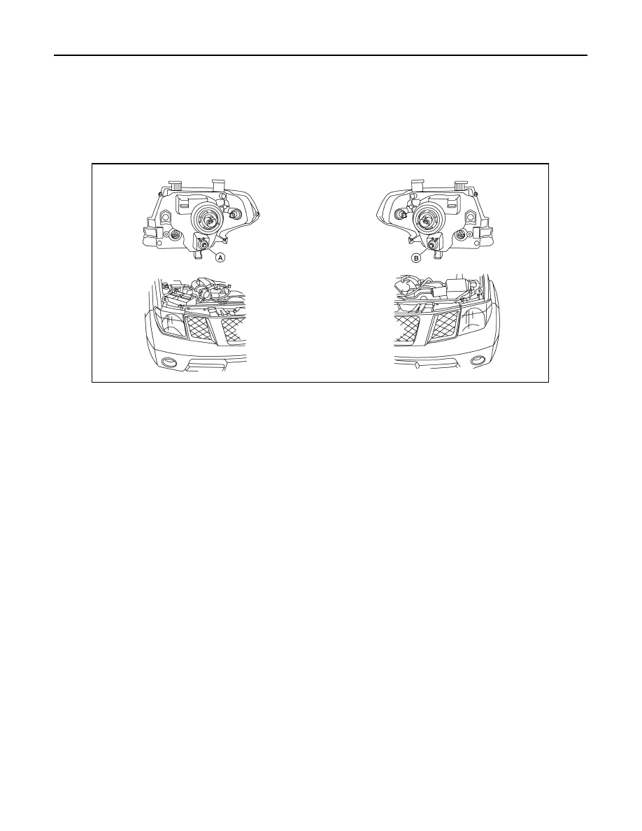
HEADLAMP : Aiming Adjustment

INFOID:0000000006247706

NOTE:

• For headlamp aiming details, refer to the regulations in your area.

• If vehicle front body has been repaired and/or the front combination lamp has been replaced, check head-

lamp aiming.

• Before performing aiming adjustment, check the following:

- Confirm headlamp aiming switch is set to "0" (zero) position.

- Ensure all tires are inflated to correct pressure.

- Place vehicle and screen on level surface.

- Ensure there is no load in vehicle other than the driver (or equivalent weight placed in driver's position).

Coolant and engine oil filled to correct level, and fuel tank full.

- Confirm spare tire, jack and tools are properly stowed.

- Aim each headlamp individually and ensure other headlamp beam pattern is blocked from screen.

- Use adjusting screw to perform aiming adjustment

LOW BEAM AND HIGH BEAM

A. Headlamp RH adjustment screw

B. Headlamp LH adjustment screw

AWKIA1436GB

2011 Pathfinder

ADJUSTMENT AND INSPECTION

EXL-143

< REMOVAL AND INSTALLATION >

C

D

E

F

G

H

I

J

K

M

A

B

EXL

N

O

P

Aiming Chart

NOTE:

• By regulation, no means for horizontal aim adjustment is provided from the factory; only vertical aim is

adjustable.

• Basic illuminating area for evaluation and/or adjustment should be within range shown on aiming chart. 
1. Use adjustment screw to perform aiming adjustment.

Cover the opposite lamp and ensure fog lamps, if equipped, are turned off.

CAUTION:

Do not tighten adjustment screw beyond specified torque or damage may occur.

2. Adjust beam pattern until cut-off line (top edge of illumination area) is positioned at the specified height off

ground. Measure cut-off line within distance J on H-line. See aiming chart.

FRONT FOG LAMP
FRONT FOG LAMP : Aiming Adjustment

INFOID:0000000006247707

The fog lamp is a semi-sealed beam type which uses a replaceable halogen bulb. Before performing aiming

adjustment, make sure of the following.

• Keep all tires inflated to correct pressure.

WKIA4885E

1

Adjustment screen

2

Headlamp bulb center (HV point)

A

Minimum acceptable vertical aim di-
mension (see aiming chart)

B

Maximum acceptable vertical aim 
dimension (see aiming chart)

C

H-V point

D

Distance of headlamp aiming screen 
from vehicle 7.62 m (25 ft.)

E

Maximum aim evaluation distance 
from vertical center on aiming 
screen 399mm (3

°

 R).

F

Minimum aim evaluation distance 
from vertical center on aiming 
screen 133 mm (1

°

R)

G

Aim evaluation area

H

Horizontal aiming evaluation line. 

Right

A (Minimum acceptable vertical aim dimension)

-3.3 mm (0.13 in)

0.025

°

 up 

B (Maximum acceptable vertical aim dimension)  36.6 mm (1.44 in)

0.275

°

 down

Adjustment torque

1.67 N.m (17 kg-cm, 14.8 in-lb)

2011 Pathfinder

EXL-144

< REMOVAL AND INSTALLATION >

ADJUSTMENT AND INSPECTION

• Place vehicle on level ground.

• See that vehicle is unloaded (except for full levels of coolant, engine oil and fuel, and spare tire, jack, and

tools). Have the driver or equivalent weight placed in driver seat.

Adjust aiming in the vertical direction by turning the adjustment

screw.

NOTE:

Use a Phillips screwdriver to adjust. Turn screw clockwise to raise

pattern and counterclockwise to lower pattern.

1. Set the distance between the screen and the center of the fog

lamp lens as shown.

2. Turn front fog lamps ON.
3. Remove front portion of fender protector(s) for adjustment screw access. Refer to 

EXT-25, "Removal and

Installation of Front Fender Protector"

4. Adjust front fog lamps using adjustment screw so that the top

edge of the high intensity zone is 100 mm (4 in) below the height

of the fog lamp centers as shown.

• When performing adjustment, if necessary, cover the head-

lamps and opposite fog lamp.

LKIA0572E

MEL327G

MEL328G

2011 Pathfinder

HEADLAMP

EXL-145

< UNIT REMOVAL AND INSTALLATION >

C

D

E

F

G

H

I

J

K

M

A

B

EXL

N

O

P

UNIT REMOVAL AND INSTALLATION

HEADLAMP

Bulb Replacement

INFOID:0000000006247708

CAUTION:

Leaving bulb removed from the headlamp housing for a long period of time can deteriorate the perfor-

mance of the lens and reflector (dirt, clouding). Always prepare a new bulb and have it on hand when

replacing a bulb.

HEADLAMP

Removal

NOTE:

Reach through engine room for bulb replacement access. 
1. Turn front headlamp switch OFF.
2. Disconnect the electrical connector.
3. Rotate the headlamp bulb retaining ring counterclockwise and remove.
4. Pull the headlamp bulb straight out from the front combination lamp.

CAUTION:

Grasp only the plastic base when handling the bulb. Never touch the glass envelope.

Installation

Installation is in the reverse order of removal.

CAUTION:

After installing bulb, be sure to install the bulb socket and plastic cap securely to ensure watertight-

ness.

FRONT TURN SIGNAL/PARKING LAMP

Removal

NOTE:

Reach through engine room for bulb replacement access.
1. Turn the bulb socket counterclockwise to unlock it.
2. Pull the bulb to remove it from the socket.

Installation

Installation is in the reverse order of removal.

CAUTION:

After installing the bulb, be sure to install the bulb socket securely to ensure watertightness.

FRONT SIDE MARKER LAMP

Removal

NOTE:

Reach through engine room for bulb replacement access.
1. Turn the bulb socket counterclockwise to unlock it.
2. Pull the bulb to remove it from the socket.

Installation

Installation is in the reverse order of removal.

CAUTION:

After installing the bulb, be sure to install the bulb socket securely to ensure watertightness.

Removal and Installation

INFOID:0000000006247709

FRONT COMBINATION LAMP

Removal

1. Remove front portion of front fender protector. Refer to 

EXT-25, "Removal and Installation of Front Fender

Protector"

.

2011 Pathfinder

EXL-146

< UNIT REMOVAL AND INSTALLATION >

HEADLAMP

2. Remove the front bumper. Refer to 

EXT-15, "Removal and Installation"

.

3. Remove the front combination lamp bolts.
4. Disconnect the front combination lamp connector and remove front combination lamp.

Installation

Installation is in the reverse order of removal.

Disassembly and Assembly

INFOID:0000000006247710

FRONT COMBINATION LAMP

DISASSEMBLY

CAUTION:

Leaving bulb removed from the headlamp housing for a long period of time can deteriorate the perfor-

mance of the lens and reflector (dirt, clouding). Always prepare a new bulb and have it on hand when

replacing a bulb.

1. Rotate headlamp bulb retaining ring counterclockwise and remove.

CAUTION:

Grasp only the plastic base when handling headlamp bulb. Never touch the glass envelope.

2. Turn front turn signal/parking lamp bulb socket counterclockwise to unlock and remove socket.
3. Turn front side marker lamp bulb socket counterclockwise to unlock and remove socket.

ASSEMBLY

Installation is in the reverse order of removal.

CAUTION:

After installing bulb, be sure to install the bulb socket and plastic cap securely to ensure watertight-

ness.

Front combination lamp bolts ·: 6.0 Nm (0.61 kg-m, 53 in-lb)

AWLIA1816ZZ

1. Front combination lamp

2. Headlamp bulb

3. Headlamp bulb retaining ring

4. Wiring harness assembly

5. Front side marker lamp bulb

6. Front turn signal/parking lamp bulb

7.

Headlamp bulb sealing ring

2011 Pathfinder

OPTICAL SENSOR

EXL-147

< UNIT REMOVAL AND INSTALLATION >

C

D

E

F

G

H

I

J

K

M

A

B

EXL

N

O

P

OPTICAL SENSOR

Removal and Installation

INFOID:0000000006247711

REMOVAL

1. Remove the optical sensor and bezel from the center of the instrument panel.
2. Disconnect the optical sensor connector.
3. Remove the optical sensor from the bezel.

INSTALLATION

Installation is in the reverse order of removal.

2011 Pathfinder

EXL-148

< UNIT REMOVAL AND INSTALLATION >

FRONT FOG LAMP

FRONT FOG LAMP

Bulb Replacement

INFOID:0000000006247712

1. Partially remove the front portion of the fender protector. Refer to 

EXT-25, "Removal and Installation of

Front Fender Protector"

.

2. Disconnect fog lamp connector.
3. Turn the bulb counterclockwise to remove it.

WARNING:

• Do not touch bulb by hand while it is lit or right after being

turned off. Burning may result.

CAUTION:

• Do not touch the glass of bulb directly by hand. Keep

grease and other oily substances away from it. 

• Do not leave bulb out of fog lamp reflector for a long time

because dust, moisture smoke, etc. may affect the perfor-

mance of fog lamp. When replacing bulb, be sure to

replace it with new one.

Removal and Installation

INFOID:0000000006247713

FRONT FOG LAMP

NOTE:

The fog lamp is a semi-sealed beam type which uses a replaceable.

Removal

1. Partially remove the front portion of the front fender protector. Refer to 

EXT-25, "Removal and Installation

of Front Fender Protector"

2. Disconnect fog lamp connector.
3. Remove fog lamp screws and pull fog lamp rearward out of front

bumper.

CAUTION:

• Do not leave fog lamp assembly without bulb for a long

period of time. Dust, moisture, smoke, etc. entering the

fog lamp body may affect the performance. Remove the

bulb from the fog lamp assembly just before replacement

bulb is installed.

• Grasp only the plastic base when handling the bulb.

Never touch the glass envelope. Touching the glass could

significantly affect the bulb life and/or fog lamp perfor-

mance.

Installation

Installation is in the reverse order of removal.

NOTE:

After installation, perform front fog lamp aiming adjustment. Refer to 

EXL-143, "FRONT FOG LAMP : Aiming

Adjustment"

.

LKIA0573E

LKIA0574E

2011 Pathfinder

LIGHTING & TURN SIGNAL SWITCH

EXL-149

< UNIT REMOVAL AND INSTALLATION >

C

D

E

F

G

H

I

J

K

M

A

B

EXL

N

O

P

LIGHTING & TURN SIGNAL SWITCH

Removal and Installation

INFOID:0000000006247714

REMOVAL

1. Remove instrument lower panel LH. Refer to 

IP-11, "Exploded View"

.

2. Remove steering column cover.
3. Disconnect the lighting and turn signal switch connector.
4. While pressing tabs, pull lighting and turn signal switch toward

driver door and release from the steering column.

INSTALLATION

Installation is in the reverse order of removal.

LKIA0013E

2011 Pathfinder


Content      ..     410      411      412      413     ..