Nissan Pathfinder (2011 year). Manual - part 373


  Index      Manuals     Nissan Pathfinder (2011 year) - Service and Repair Manual


Search            copyright infringement  


Content      ..     371      372      373      374     ..


Nissan Pathfinder (2011 year). Manual - part 373


CYLINDER HEAD

EM-95

< REMOVAL AND INSTALLATION >

[VQ40DE]

C

D

E

F

G

H

I

J

K

L

M

A

EM

N

P

O

6. Remove valve oil seals using Tool.

7. If valve seat must be replaced, refer to 

EM-96, "Inspection After Disassembly"

.

8. If valve guide must be replaced, refer to 

EM-96, "Inspection After Disassembly"

.

9. Remove spark plug tube, as necessary.

• Using pair of pliers, pull spark plug tube out of cylinder head. 

CAUTION:

• Take care not to damage cylinder head.

• Once removed, spark plug tube will be deformed and cannot be reused. Do not remove it unless

absolutely necessary.

ASSEMBLY

1. When valve guide is removed, install it. Refer to 

EM-96, "Inspection After Disassembly"

.

2. When valve seat is removed, install it. Refer to 

EM-96, "Inspection After Disassembly"

.

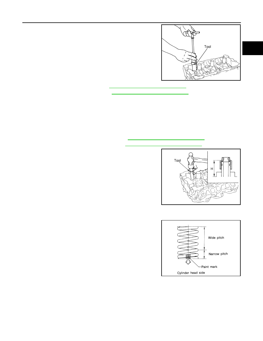
3. Install valve oil seals using Tool.

4. Install valve spring seat.
5. Install valves.

• Install it in the original position.

NOTE:

Larger diameter valves are for intake side.

6. Install valve spring (uneven pitch type).

• Install narrow pitch end (paint mark) to cylinder head side

(valve spring seat side).

7. Install valve spring retainer.

Tool number

: KV10107902 (J-38959)

WBIA0489E

Tool number

:

 (J-39386)

Height "H" (Without valve spring seat installed)

Intake and exhaust

: 14.3 - 14.9 mm (0.563 - 0.587 in)

WBIA0490E

SEM085D

2011 Pathfinder

EM-96

< REMOVAL AND INSTALLATION >

[VQ40DE]

CYLINDER HEAD

8. Install valve collet.

• Compress valve spring using Tool, attachment and adapter

using Tool. Install valve collet with magnet hand.

CAUTION:

When working, take care not to damage valve lifter holes

or valve stems.

• Tap valve stem edge lightly with plastic hammer after installa-

tion to check its installed condition.

9. Install valve lifter.

• Install it in the original position.

10. Install spark plug tube.

• Press-fit spark plug tube as follows:

a. Remove old liquid gasket adhering to cylinder head mounting hole.
b. Apply sealant to area within approximately 12 mm (0.47 in) from edge of spark plug tube press-fit side.

Use Genuine High Strength Locking Sealant or equivalent. Refer to 

GI-14, "Recommended Chemi-

cal Products and Sealants"

.

c.

Press-fit spark plug tube so that its height “H” is as specified

using suitable drift.

CAUTION:

• When press-fitting, take care not to deform spark plug

tube.

• After press-fitting, wipe off liquid gasket protruding onto

cylinder-head upper face.

11. Install spark plug.

Inspection After Disassembly

INFOID:0000000006247037

VALVE DIMENSIONS

• Check dimensions of each valve. For dimensions, refer to 

EM-132, "Standard and Limit"

.

• If dimensions are out of the standard, replace valve and check the valve seat contact. 

VALVE GUIDE CLEARANCE

Valve Stem Diameter

Measure the diameter of valve stem with micrometer.

Valve Guide Inner Diameter

Measure the inner diameter of valve guide with inside micrometer.

Tool numbers

: KV10109220 (

)

: KV10116200 (J-26336-B)
: KV10115900 (J-26336-20)

WBIA0578E

Standard press-fit height “H”

: 38.1 - 39.1 mm (1.500 - 1.539 in)

PBIC2638E

Standard

Intake

: 5.965 - 5.980 mm (0.2348 - 0.2354 in)

Exhaust

: 5.955 - 5.970 mm (0.2344 - 0.2350 in)

SEM938C

2011 Pathfinder

CYLINDER HEAD

EM-97

< REMOVAL AND INSTALLATION >

[VQ40DE]

C

D

E

F

G

H

I

J

K

L

M

A

EM

N

P

O

Valve Guide Clearance

(Valve guide clearance) = (Valve guide inner diameter) – (Valve stem diameter).

• If the calculated value exceeds the limit, replace valve and/or valve guide. 

VALVE GUIDE REPLACEMENT

When valve guide is removed, replace with oversized [0.2 mm (0.008 in)] valve guide.
1. To remove valve guide, heat cylinder head to 110

°

 to 130

°

C

(230

°

 to 266

°

F) by soaking in heated oil.

2. Drive out valve guide with a press [under a 20 kN (2 ton, 2.2 US

ton, 2.0 Imp ton) pressure] or hammer and suitable tool.

WARNING:

Cylinder head contains heat. When working, wear protec-

tive equipment to avoid getting burned.

3. Ream cylinder head valve guide hole using suitable tool.

Standard

Intake and Exhaust

: 6.000 - 6.018 mm (0.2362 - 0.2369 in)

Valve guide clearance:
Standard

Intake

: 0.020 - 0.053 mm (0.0008 - 0.0021 in)

Exhaust : 0.030 - 0.063 mm (0.0012 - 0.0025 in)

Limit

Intake

: 0.08 mm (0.003 in)

Exhaust : 0.09 mm (0.004 in)

SEM008A

SEM931C

Valve guide hole diameter (for service parts):

Intake and exhaust

: 10.175 - 10.196 mm (0.4006 - 0.4014 in)

SEM932C

2011 Pathfinder

EM-98

< REMOVAL AND INSTALLATION >

[VQ40DE]

CYLINDER HEAD

4. Heat cylinder head to 110

°

 to 130

°

C (230

°

 to 266

°

F) by soaking

in heated oil.

5. Press valve guide from camshaft side to the dimensions as

shown using suitable tool.

WARNING:

Cylinder head contains heat. When working, wear protec-

tive equipment to avoid getting burned.

6. Apply reamer finish to valve guide using suitable tool.

VALVE SEAT CONTACT

• After confirming that the dimensions of valve guides and valves are

within the specifications, perform this procedure.

• Apply prussian blue (or white lead) onto contacting surface of valve

seat to check the condition of the valve contact on the surface.

• Check if the contact area band is continuous all around the circum-

ference.

• If not, grind to adjust valve fitting and check again. If the contacting

surface still has “NG” conditions even after the re-check, replace

valve seat. 

VALVE SEAT REPLACEMENT

When valve seat is removed, replace with oversized [0.5 mm (0.020 in)] valve seat.
1. Bore out old seat until it collapses. Boring should not continue beyond the bottom face of the seat recess

in cylinder head. Set the machine depth stop to ensure this. Refer to 

EM-132, "Standard and Limit"

.

CAUTION:

Do not scratch cylinder head by excessive boring.

SEM008A

Projection “L”

Intake and exhaust

: 12.6 - 12.8 mm (0.496 - 0.504 in)

SEM950E

Standard:

Intake and exhaust

: 6.000 - 6.018 mm (0.2362 - 0.2369 in)

SEM932C

SBIA0322E

2011 Pathfinder

CYLINDER HEAD

EM-99

< REMOVAL AND INSTALLATION >

[VQ40DE]

C

D

E

F

G

H

I

J

K

L

M

A

EM

N

P

O

2. Ream cylinder head recess diameter for service valve seat.

• Be sure to ream in circles concentric to valve guide center.

This will enable valve to fit correctly.

3. Heat cylinder head to 110

°

 to 130

°

C (230

°

 to 266

°

F) by soaking

in heated oil.

4. Provide valve seats cooled well with dry ice. Force fit valve seat into cylinder head.

WARNING:

• Cylinder head contains heat. When working, wear protective equipment to avoid getting burned.

CAUTION:

• Avoid directly touching cold valve seats.

5. Finish seat to the specified dimensions using suitable tool. Refer

to 

EM-132, "Standard and Limit"

.

CAUTION:

When using valve seat cutter, firmly grip cutter handle with

both hands. Then, press on the contacting surface all

around the circumference to cut in a single drive. Improper

pressure on cutter or cutting many different times may

result in staged valve seat. 

6. Using compound, grind to adjust valve fitting. 
7. Check again for normal contact. 

VALVE SPRING SQUARENESS

• Set try square along the side of valve spring and rotate spring.

Measure the maximum clearance between the top face of spring

and try square.

• If it exceeds the limit, replace valve spring.

VALVE SPRING DIMENSIONS AND VALVE SPRING PRESSURE LOAD

Oversize [0.5 mm (0.020 in)]

Intake

: 38.500 - 38.516 mm (1.5157 - 1.5164 in)

Exhaust

: 32.700 - 32.716 mm (1.2874 - 1.2880 in)

SEM795A

SEM008A

SEM934C

Limit

: 2.1 mm (0.083 in)

PBIC0080E

2011 Pathfinder

EM-100

< REMOVAL AND INSTALLATION >

[VQ40DE]

CYLINDER HEAD

• Check valve spring pressure at the specified spring height.

• If the installation load or load with valve open is out of the standard, replace valve spring.

Standard:

Intake and exhaust

Free height

: 47.07 mm (1.8531 in)

Installation height

: 37.00 mm (1.4567 in)

Installation load

: 166 - 188 N (16.9 - 19.2 kg, 37 - 42 lb)

Height during valve open

: 27.20 mm (1.0709 in)

Load with valve open

: 373 - 421 N (38.0 - 42.9 kg, 84 - 95 lb)

SEM113

2011 Pathfinder

ENGINE ASSEMBLY

EM-101

< UNIT REMOVAL AND INSTALLATION >

[VQ40DE]

C

D

E

F

G

H

I

J

K

L

M

A

EM

N

P

O

UNIT REMOVAL AND INSTALLATION

ENGINE ASSEMBLY

Exploded View

INFOID:0000000006247038

Removal and Installation

INFOID:0000000006247039

WARNING:

• Situate vehicle on a flat and solid surface.

• Place chocks at front and back of rear wheels.

• For engines not equipped with engine slingers, attach proper slingers and bolts described in PARTS

CATALOG.

1.

Rear engine mounting insulator 4WD 2. Rear engine mounting insulator 2WD 3. LH engine mounting bracket (upper)

4.

LH heat shield plate

5. LH engine mounting insulator

6. LH engine mounting bracket (lower)

7.

RH engine mounting bracket (lower)

8. RH engine mounting insulator

9. RH heat shield plate

10. RH engine mounting bracket (upper)

AWBIA0721GB

2011 Pathfinder

EM-102

< UNIT REMOVAL AND INSTALLATION >

[VQ40DE]

ENGINE ASSEMBLY

• When lifting vehicle, ensure that the front end and the rear of the vehicle are well balanced.

CAUTION:

• Always be careful to work safely, avoid forceful or uninstructed operations.

• Do not start working until exhaust system and engine coolant are cooled sufficiently.

• If items or work required are not covered by the engine section, follow the procedures in the applica-

ble sections.

• Always use the support point specified for lifting.

• Use either 2-point lift type or separate type lift. If board-on type is used for unavoidable reasons,

support the rear axle jacking point with transmission jack or similar tool before starting work, in

preparation for the backward shift of center of gravity.

• For supporting points for lifting and jacking point at rear axle, refer to 

GI-29, "Garage Jack and

Safety Stand"

.

NOTE:

When removing components such as hoses, tubes/lines, etc., cap or plug openings to prevent fluid from spill-

ing.

REMOVAL

Preparation

1. Remove front and rear engine under covers, if equipped. Refer to 

EXT-15, "Removal and Installation"

.

2. Drain engine oil. Refer to 

LU-9, "Changing Engine Oil"

.

3. Remove engine oil filter.
4. Drain engine coolant. Refer to 

CO-13, "Changing Engine Coolant"

.

5. Release fuel pressure. Refer to 

EC-484, "Fuel Pressure Check"

.

6. Remove the engine hood. Refer to 

DLK-193, "Removal and Installation of Hood Assembly"

.

7. Disconnect the battery negative terminal. Refer to 

PG-76, "Removal and Installation"

.

8. Remove engine room cover. Refer to 

EM-25, "Removal and Installation"

.

9. Remove the air duct and resonator assembly and air cleaner case assembly. Refer to 

EM-26, "Removal

and Installation"

.

10. Disconnect brake booster vacuum hose between vehicle and engine and set it aside.
11. Remove front grille. Refer to 

EXT-20, "Removal and Installation"

.

12. Remove the radiator assembly and hoses. Refer to 

CO-18, "Removal and Installation"

.

13. Remove the drive belts. Refer to 

EM-14, "Removal and Installation"

14. Remove the engine cooling fan and shroud. Refer to 

CO-21, "Removal and Installation (Crankshaft driven

type)"

.

15. Disconnect the engine room harness from the engine side and set it aside.
16. Disconnect the engine harness grounds.
17. Disconnect the reservoir tank for power steering from engine and move it aside.
18. Disconnect power steering oil pump from engine. Move it from its location and secure with a rope. Refer to

ST-24, "Removal and Installation"

19. Remove the A/C compressor bolts and set aside without disconnecting the A/C hoses. Refer to 

HA-38,

"Removal and Installation for Compressor"

.

20. Disconnect EVAP line.
21. Disconnect the fuel hose at the engine side connection. Refer to 

EM-47, "Removal and Installation"

.

22. Disconnect the heater hoses at cowl, and install plugs to avoid leakage of engine coolant.
23. Remove the A/T oil level indicator and indicator tube.
24. Remove front final drive assembly (4WD models). Refer to 

DLN-356, "Removal and Installation"

.

25. Remove three way catalyst. Refer to 

EM-32, "Removal and Installation (Three Way Catalyst)"

.

2011 Pathfinder


Content      ..     371      372      373      374     ..