Nissan Pathfinder (2011 year). Manual - part 366


  Index      Manuals     Nissan Pathfinder (2011 year) - Service and Repair Manual


Search            copyright infringement  


Content      ..     364      365      366      367     ..


Nissan Pathfinder (2011 year). Manual - part 366


OIL PAN AND OIL STRAINER

EM-39

< REMOVAL AND INSTALLATION >

[VQ40DE]

C

D

E

F

G

H

I

J

K

L

M

A

EM

N

P

O

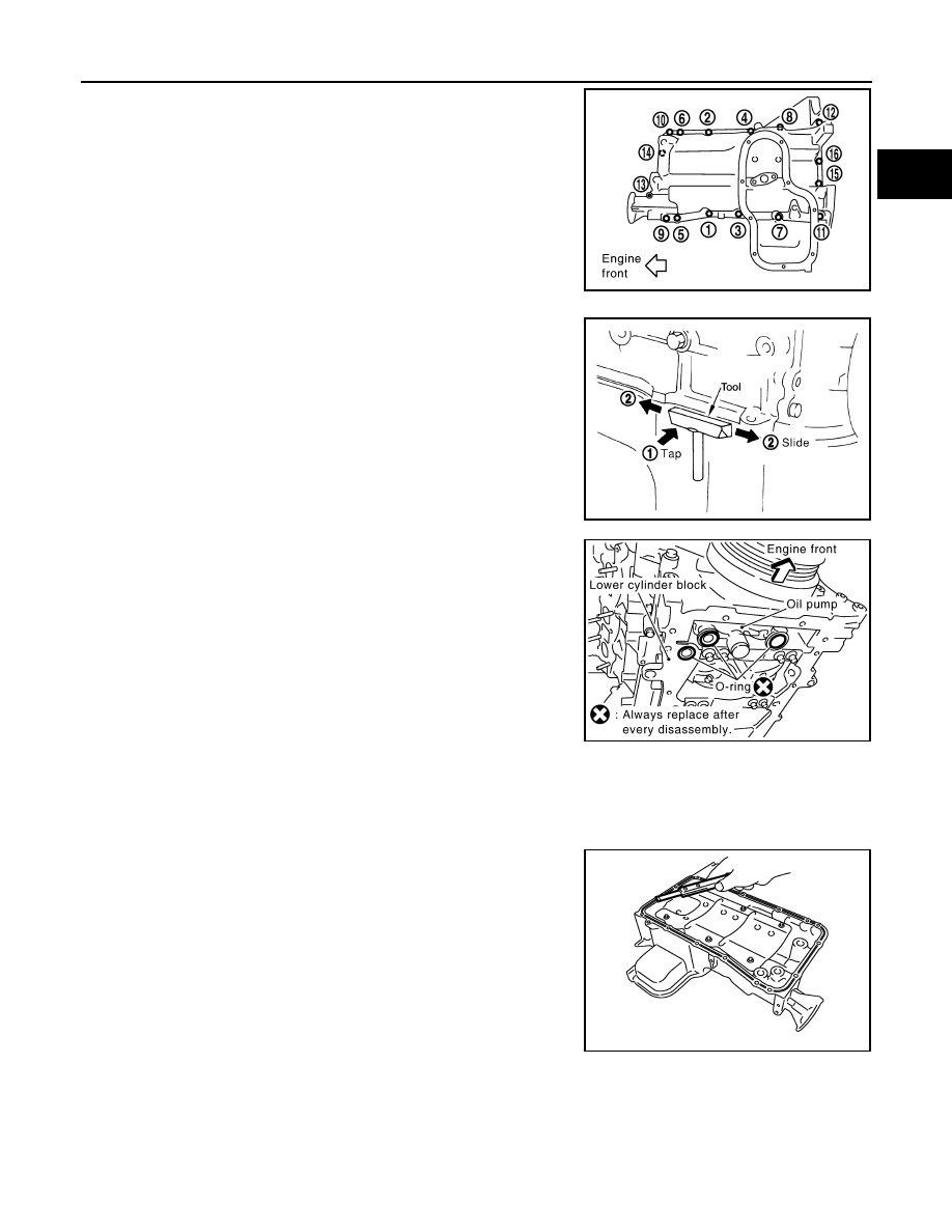
19. Loosen oil pan (upper) bolts with power tool in reverse order as

shown.

• Insert Tool between oil pan (upper) and lower cylinder block.

Tap (1) Tool to insert it and then slide (2) it by tapping on the

side as shown.

CAUTION:

Be careful not to damage mating surfaces.

20. Remove O-rings from bottom of lower cylinder block and oil

pump.

CAUTION:

• Do not reuse the three O-rings.

• Install a new O-ring in the upper oil pan and two new O-

rings in the front cover.

INSPECTION AFTER REMOVAL

Clean oil strainer if any object attached.

INSTALLATION (UPPER)

1. Install oil pan (upper) as follows:
a. Use scraper to remove old liquid gasket from mating surfaces.

• Also remove the old liquid gasket from mating surface of lower

cylinder block.

• Remove old liquid gasket from the bolt holes and threads.

CAUTION:

Do not scratch or damage the mating surfaces when clean-

ing off old liquid gasket.

PBIC2887E

Tool number

: KV10111100 (J-37228)

WBIA0566E

PBIC2885E

PBIC2884E

2011 Pathfinder

EM-40

< REMOVAL AND INSTALLATION >

[VQ40DE]

OIL PAN AND OIL STRAINER

b. Install new O-rings on the bottom of lower cylinder block and oil

pump.

CAUTION:

• Do not reuse the three O-rings.

• Install a new O-ring in the upper oil pan and two new O-

rings in the front cover.

c.

Apply a continuous bead of liquid gasket using Tool to the lower

cylinder block mating surfaces of oil pan (upper) as shown.

Use Genuine RTV Silicone Sealant or equivalent. Refer to

GI-14, "Recommended Chemical Products and Sealants"

.

CAUTION:

• For bolt holes with   mark, apply liquid gasket outside

the hole.

• Apply a bead of 4.5 to 5.5 mm (0.177 to 0.217 in) in diame-

ter to area (A).

• Attaching should be done within 5 minutes after coating.

d. Install oil pan (upper).

CAUTION:

• Do not reuse the three O-rings.

• Install a new O-ring in the upper oil pan and two new O-rings in the front cover.

• Install avoiding misalignment of both oil pan gaskets and O-rings.

• Tighten oil pan (upper) bolts in numerical order as shown.

• There are two types of bolts. 

e. Tighten transmission joint bolts. Refer to 

TM-193, "2WD : Exploded View"

 (2WD models), 

TM-196, "4WD

: Exploded View"

 (4WD models).

2. Install oil strainer to oil pan (upper).
3. Installation of the remaining components is in the reverse order of removal.

INSPECTION AFTER INSTALLATION

• Before starting engine, check oil/fluid levels including engine coolant and engine oil. If less than required

quantity, fill to the specified level. Refer to 

MA-18, "FOR USA AND CANADA : Fluids and Lubricants"

 (United

States and Canada) and 

MA-20, "FOR MEXICO : Fluids and Lubricants"

 (Mexico).

• Use procedure below to check for fuel leakage.

• Turn ignition switch ON (with engine stopped). With fuel pressure applied to fuel piping, check for fuel leak-

age at connection points.

• Start engine. With engine speed increased, check again for fuel leakage at connection points.

• Run engine to check for unusual noise and vibration.

NOTE:

If hydraulic pressure inside timing chain tensioner drops after removal and installation, slack in the guide

may generate a pounding noise during and just after engine start. However, this is normal. Noise will stop

after hydraulic pressure rises.

PBIC2885E

Tool number

: WS39930000 (

)

PBIC2886E

M8 

×

 100 mm (3.97 in)

: 7, 11, 12, 13

M8 

×

 25 mm (0.98 in)

: All except the above

PBIC2887E

2011 Pathfinder

OIL PAN AND OIL STRAINER

EM-41

< REMOVAL AND INSTALLATION >

[VQ40DE]

C

D

E

F

G

H

I

J

K

L

M

A

EM

N

P

O

• Warm up engine thoroughly to make sure there is no leakage of fuel, exhaust gas, or any oils/fluids including

engine oil and engine coolant.

• Bleed air from passages in lines and hoses, such as in cooling system.

• After cooling down engine, again check oil/fluid levels including engine oil and engine coolant. Refill to spec-

ified level, if necessary.

• Summary of the inspection items:

*Power steering fluid, brake fluid, etc.

Item

Before starting engine

Engine running

After engine stopped

Engine coolant

Level

Leakage

Level

Engine oil

Level

Leakage

Level

Transmission/
transaxle fluid 

A/T and CVT Models

Leakage

Level/Leakage

Leakage

M/T Models

Level/Leakage

Leakage

Level/Leakage

Other oils and fluids*

Level

Leakage

Level

Fuel

Leakage

Leakage

Leakage

Exhaust gas

Leakage

2011 Pathfinder

EM-42

< REMOVAL AND INSTALLATION >

[VQ40DE]

IGNITION COIL

IGNITION COIL

Exploded View

INFOID:0000000006247012

Removal and Installation

INFOID:0000000006247013

REMOVAL (LH)

1. Remove engine room cover. Refer to 

EM-25, "Removal and Installation"

.

2. Move aside harness, harness bracket, and hoses located above ignition coil.
3. Disconnect the harness connector from the ignition coil.
4. Remove the ignition coil.

CAUTION:

Do not shock ignition coil.

INSTALLATION (LH)

Installation is in the reverse order of removal.

REMOVAL (RH)

1. Remove intake manifold collector. Refer to 

EM-27, "Removal and Installation"

.

2. Move aside harness, harness bracket, and hoses located above ignition coil.
3. Disconnect the harness connector from the ignition coil.
4. Remove the ignition coil.

CAUTION:

Do not shock ignition coil.

INSTALLATION (RH)

Installation is in the reverse order of removal.

1.

Ignition coil

2.

Spark plug

PBIC2901E

2011 Pathfinder

ROCKER COVER

EM-43

< REMOVAL AND INSTALLATION >

[VQ40DE]

C

D

E

F

G

H

I

J

K

L

M

A

EM

N

P

O

ROCKER COVER

Exploded View

INFOID:0000000006247014

Removal and Installation

INFOID:0000000006247015

REMOVAL (LH)

1. Remove the engine room cover. Refer to 

EM-25, "Removal and Installation"

.

2. Remove air duct and resonator assembly. Refer to 

EM-26, "Exploded View"

.

3. Separate engine harness removing their brackets from rocker covers.
4. Remove harness bracket from cylinder head, if necessary. 
5. Disconnect and remove the intake valve timing control solenoid valve (LH bank). Refer to 

EM-53,

"Exploded View"

.

6. Remove the ignition coils. Refer to 

EM-42, "Removal and Installation"

.

7. Remove the PCV hoses from rocker covers.
8. Remove the oil filler cap from rocker cover (LH), if necessary.

1.

Oil filler cap

2.

PCV hose

3.

PCV valve

4.

O-ring

5.

Rocker cover (RH)

6.

PCV hose

7.

Rocker cover gasket (RH)

8.

Rocker cover gasket (LH)

9.

Rocker cover (LH)

10. PCV hose

PBIC2905E

2011 Pathfinder

EM-44

< REMOVAL AND INSTALLATION >

[VQ40DE]

ROCKER COVER

9. Loosen the rocker cover bolts with power tool in reverse order

as shown.

: Front

10. Remove rocker cover.
11. Remove rocker cover gaskets from rocker covers.
12. Use scraper to remove all traces of liquid gasket from cylinder head and camshaft bracket (No. 1).

CAUTION:

Do not scratch or damage the mating surface when cleaning off old liquid gasket.

INSTALLATION (LH)

1. Apply liquid gasket using Tool to joint part among rocker cover,

cylinder head and camshaft bracket (No. 1) as follows:

CAUTION:

• The components must be installed within 5 minutes of the

liquid gasket application. Then allow 30 minutes for the

liquid gasket to set before operating the engine.

• Remove water, oil, dust, dirt, or other foreign material on

all sealing surfaces prior to installation. 

• Use Genuine RTV Silicone Sealant or equivalent. Refer to

GI-14, "Recommended Chemical Products and Sealants"

.

NOTE:

The figure shows an example of LH side [zoomed in shows

camshaft bracket (No. 1)].

a. Apply liquid gasket to joint part of camshaft bracket (a) (No. 1)

and cylinder head.

b. Apply liquid gasket (b) to the figure (a) squarely.

2. Install new rocker cover gasket to rocker cover.
3. Install the rocker cover.

• Check to be sure rocker cover gasket is not dropped from installation groove of rocker cover.

4. Tighten the rocker cover bolts in two steps in numerical order as

shown.

: Front

5. Install the oil filler cap to rocker cover (LH), if removed.

AWBIA0729ZZ

PBIC2474E

1st step

: 1.96 N·m (0.20 kg-m, 17 in-lb)

2nd step

: 8.33 N·m (0.85 kg-m, 74 in-lb)

AWBIA0729ZZ

2011 Pathfinder

ROCKER COVER

EM-45

< REMOVAL AND INSTALLATION >

[VQ40DE]

C

D

E

F

G

H

I

J

K

L

M

A

EM

N

P

O

6. Install the PCV hose.

• Insert PCV hose by 25 to 30 mm (0.98 to 1.18 in) from connector end.

• When installing, be careful not to twist or come in contact with other parts.

7. Installation of the remaining components is in the reverse order of removal.

• Check engine oil level and adjust as necessary. Refer to 

LU-8, "Inspection"

.

REMOVAL (RH)

1. Remove the intake manifold collector. Refer to 

EM-27, "Removal and Installation"

.

CAUTION:

Perform this step when engine is cold.

2. Separate engine harness removing their brackets from rocker covers.
3. Remove harness bracket from cylinder head (RH). Refer to 

EM-90, "Removal and Installation"

.

4. Disconnect and remove the intake valve timing control solenoid valve (RH bank). Refer to 

EM-53,

"Exploded View"

.

5. Remove the ignition coils. Refer to 

EM-42, "Removal and Installation"

.

6. Remove the PCV hoses from rocker cover.
7. Remove the PCV valve and O-ring from rocker cover (RH), if necessary.
8. Loosen the rocker cover bolts with power tool in reverse order

as shown.

: Front

9. Remove rocker cover.
10. Remove rocker cover gaskets from rocker covers.
11. Use scraper to remove all traces of liquid gasket from cylinder head and camshaft bracket (No. 1).

CAUTION:

Do not scratch or damage the mating surface when cleaning off old liquid gasket.

INSTALLATION (RH)

AWBIA0730ZZ

2011 Pathfinder

EM-46

< REMOVAL AND INSTALLATION >

[VQ40DE]

ROCKER COVER

1. Apply liquid gasket using Tool to joint part among rocker cover,

cylinder head and camshaft bracket (No. 1) as follows:

CAUTION:

• The components must be installed within 5 minutes of the

liquid gasket application. Then allow 30 minutes for the

liquid gasket to set before operating the engine.

• Remove water, oil, dust, dirt, or other foreign material on

all sealing surfaces prior to installation. 

• Use Genuine RTV Silicone Sealant or equivalent. Refer to

GI-14, "Recommended Chemical Products and Sealants"

.

NOTE:

The figure shows an example of LH side [zoomed in shows

camshaft bracket (No. 1)].

a. Apply liquid gasket to joint part of camshaft bracket (a) (No. 1)

and cylinder head.

b. Apply liquid gasket (b) to the figure (a) squarely.

2. Install new rocker cover gasket to rocker cover.
3. Install the rocker cover.

• Check to be sure rocker cover gasket is not dropped from installation groove of rocker cover.

4. Tighten the rocker cover bolts in two steps in numerical order as

shown.

: Front

5. Install new O-ring and PCV valve to rocker cover (RH), if removed.

CAUTION:

Do not reuse O-ring.

6. Install the PCV hose.

• Insert PCV hose by 25 to 30 mm (0.98 to 1.18 in) from connector end.

• When installing, be careful not to twist or come in contact with other parts.

7. Installation of the remaining components is in the reverse order of removal.

PBIC2474E

1st step

: 1.96 N·m (0.20 kg-m, 17 in-lb)

2nd step

: 8.33 N·m (0.85 kg-m, 74 in-lb)

AWBIA0730ZZ

2011 Pathfinder


Content      ..     364      365      366      367     ..