Nissan Pathfinder (2011 year). Manual - part 350
EC-854
< DTC/CIRCUIT DIAGNOSIS >
[VK56DE]
P1553 BATTERY CURRENT SENSOR
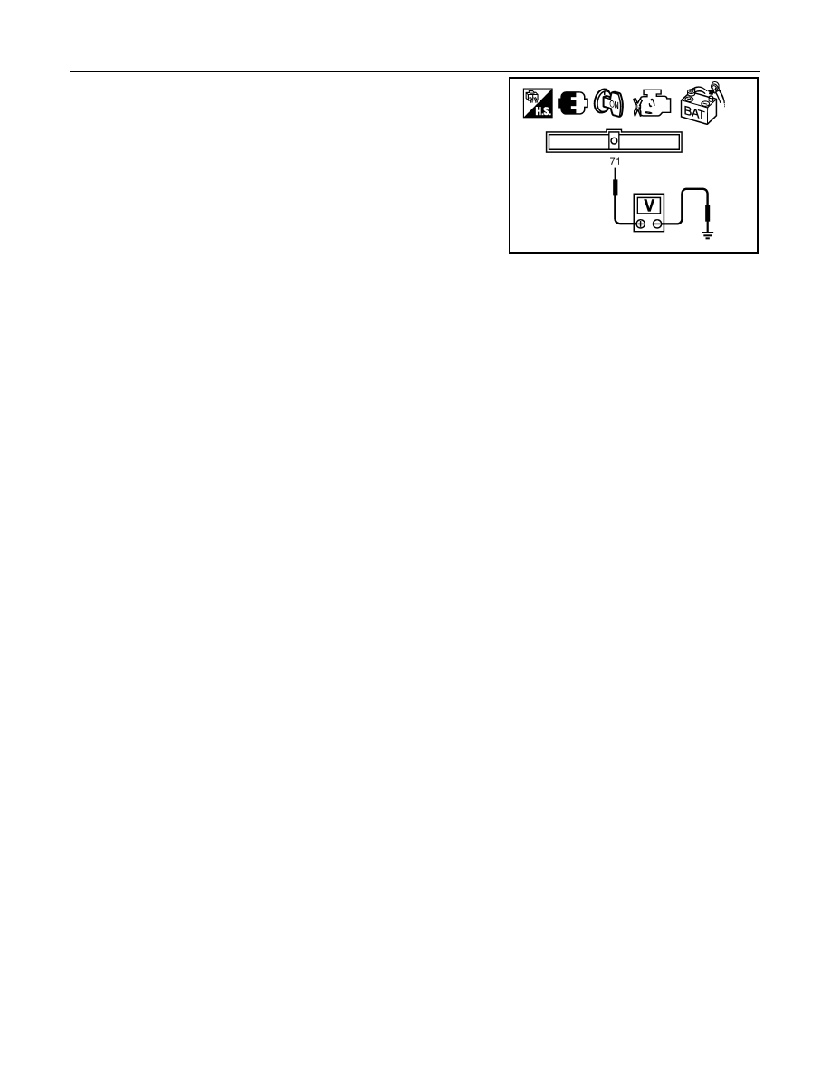
5. Check voltage between ECM terminal 71 (battery current sensor
signal) and ground.
6. If NG, replace battery negative cable assembly.
Voltage: Approximately 2.5 V
PBIB2617E
2011 Pathfinder