Index Manuals Nissan Pathfinder (2011 year) - Service and Repair Manual
Search copyright infringement
Content .. 300 301 302 303 ..
Nissan Pathfinder (2011 year). Manual - part 302
EC-470
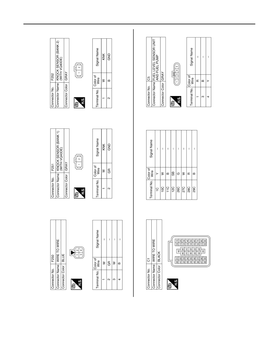
< WIRING DIAGRAM >
[VQ40DE]
ENGINE CONTROL SYSTEM
AABIA0431GB
2011 Pathfinder