Nissan Pathfinder (2011 year). Manual - part 212
DLN-234
< DTC/CIRCUIT DIAGNOSIS >
[TRANSFER: TX15B]
P1819 TRANSFER CONTROL DEVICE
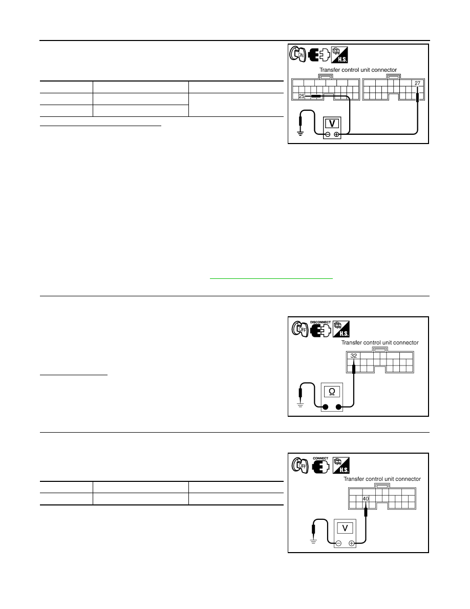
4. Turn ignition switch “ON”. (Do not start engine.)
5. Check voltage between transfer control unit harness connector
terminals and ground.
Are the inspection results normal?
YES
>> GO TO 2.
NO
>> Check the following. If any items are damaged, repair
or replace damaged parts.
• 10A fuse (No. 57, located in the fuse and relay box).
• 40A fuse (No.
J
, located in the fuse and fusible link box).
• Harness for short or open between battery and transfer shut off relay 1 harness connector E156
terminal 3.
• Harness for short or open between transfer control unit harness connector M166 terminal 27
and transfer shut off relay 1 harness connector E156 terminal 5.
• Harness for short or open between ignition switch and transfer shut off relay 1 harness connec-
tor E156 terminal 1.
• Harness for short or open between transfer shut off relay 1 harness connector E156 terminal 2
and ground.
• Harness for short or open between ignition switch and transfer control unit harness connector
M165 terminal 25.
• Battery and ignition switch.
• Transfer shut off relay 1. Refer to
DLN-208, "Component Inspection"
2.
CHECK GROUND CIRCUIT
1. Turn ignition switch "OFF".
2. Disconnect transfer control unit harness connector.
3. Check continuity between transfer control unit harness connec-
tor M166 terminal 32 and ground.
Also check harness for short to power.
Is there continuity?
YES
>> GO TO 3.
NO
>> Repair open circuit or short to power in harness or con-
nectors.
3.
CHECK POWER SUPPLY SIGNAL
1. Turn ignition switch “OFF”. (Stay for at least 5 seconds.)
2. Connect transfer control unit harness connector.
3. Check voltage between transfer control unit harness connector
terminal and ground.
Connector
Terminal
Voltage (Approx.)
M165
25 - Ground
Battery voltage
M166
27 - Ground
SDIA3372E
Continuity should exist.
SDIA2818E
Connector
Terminal
Voltage (Approx.)
M166
40 - Ground
Battery voltage
SDIA2819E
2011 Pathfinder