Nissan Pathfinder (2011 year). Manual - part 134


  Index      Manuals     Nissan Pathfinder (2011 year) - Service and Repair Manual


Search            copyright infringement  


Content      ..     132      133      134      135     ..


Nissan Pathfinder (2011 year). Manual - part 134


ENGINE COOLANT

CO-43

< PERIODIC MAINTENANCE >

[VK56DE]

C

D

E

F

G

H

I

J

K

L

M

A

CO

N

P

O

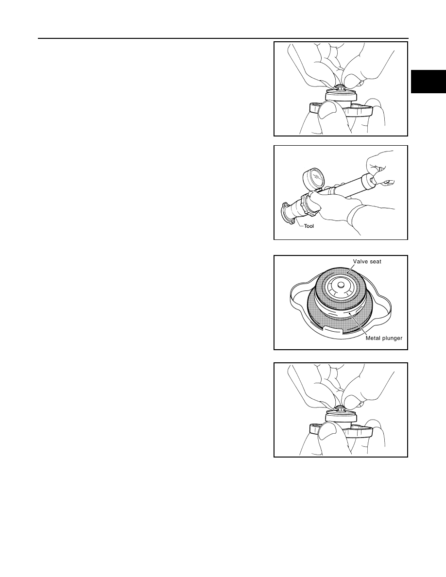
2. Pull the negative-pressure valve to open it and check that it

closes completely when released.

• Check that there is no dirt or damage on the valve seat of the

reservoir cap negative-pressure valve.

• Check that there are no abnormalities in the opening and clos-

ing conditions of the negative-pressure valve.

3. Check reservoir cap relief pressure using suitable tool and Tool.

NOTE:

• Apply engine coolant to the cap seal surface. 

• Replace the reservoir cap if there is any damage in the nega-

tive-pressure valve, or if the open-valve pressure is outside of

the limit.

CHECKING RADIATOR CAP

• Check valve seat of radiator cap.

- Replace the cap if the metal plunger cannot be seen around the

edge of the black rubber gasket.

- Replace the cap if deposits of waxy residue or other foreign mate-

rial are on the black rubber gasket or the metal retainer.

NOTE:

Thoroughly wipe out the radiator filler neck to remove any waxy

residue or foreign material.

• Pull the negative-pressure valve to open it and check that it closes

completely when released.

- Check that there is no dirt or damage on the valve seat of the radi-

ator cap negative-pressure valve.

- Make sure that the valve operates properly while opening and

closing.

SMA967B

Tool number

: —  (J-24460-92)

Standard: 98 – 118 kPa (1.0 – 1.2 kg/cm

2

, 14 – 17 psi)

WBIA0570E

PBIC2816E

SMA967B

2011 Pathfinder

CO-44

< PERIODIC MAINTENANCE >

[VK56DE]

ENGINE COOLANT

• Check radiator cap relief pressure using suitable tool and Tool.

- When connecting the radiator cap to the tester, apply water or coolant to the cap seal surface.

- Replace radiator cap if there is an abnormality in the negative-pressure valve, or if the open-valve pressure

is outside of the standard values.

• Replace the radiator cap if it exceeds the specifications in the above tests.

CAUTION:

When installing the radiator cap, thoroughly wipe out the radiator filler neck to remove waxy residue

or foreign material. 

CHECKING RADIATOR

Check radiator for mud or clogging. If necessary, clean radiator as follows.

CAUTION:

• Be careful not to bend or damage the radiator fins.

• When radiator is cleaned without removal, remove all surrounding parts such as cooling fan, radia-

tor shroud and horns. Then tape the harness and electrical connectors to prevent water from enter-

ing.

1. Spray water to the back side of the radiator core using a side to side motion from the top down. 
2. Stop spraying when debris no longer flows from radiator core. 
3. Blow air into the back side of radiator core using a side to side motion from the top down.

• Use compressed air lower than 490 kPa (5 kg/cm

2

, 71 psi) and keep distance more than 30 cm (11.8 in). 

4. Continue to blow air until no water sprays out.
5. Check for coolant leaks. Repair as necessary.

Changing Engine Coolant

INFOID:0000000006247874

WARNING:

• To avoid being scalded, never change the coolant when the engine is hot.

• Wrap a thick cloth around the cap to carefully remove the cap. First, turn the cap a quarter of a turn

to release any built-up pressure, then push down and turn the cap all the way to remove it.

DRAINING ENGINE COOLANT

1. Turn ignition switch ON and set temperature control lever all the way to HOT position or the highest tem-

perature position. Wait 10 seconds and turn ignition switch OFF.

2. Remove the engine under cover using power tool.
3. Open the radiator drain plug at the bottom of the radiator, and

remove the reservoir cap. This is the only step required when

partially draining the cooling system (radiator only). 

CAUTION:

• Perform this step when the engine is cold.

• Do not allow the coolant to contact the drive belts.

Tool number

: EG17650301 (J-33984-A)

Standard: 98 – 118 kPa (1.0 – 1.2 kg/cm

2

, 14 – 17 psi)

WBIA0570E

LLIA0070E

2011 Pathfinder

ENGINE COOLANT

CO-45

< PERIODIC MAINTENANCE >

[VK56DE]

C

D

E

F

G

H

I

J

K

L

M

A

CO

N

P

O

4. When draining all of the coolant in the system for engine

removal or repair, it is necessary to drain the cylinder block.

Remove the RH cylinder block drain plug to drain the right bank,

the oil cooler hose to drain the left bank as shown. 

CAUTION:

Do not reuse copper sealing washers.

NOTE:

For Canada, the drain plug as shown is replaced by a block

heater.

5. Remove the reservoir tank to drain the engine coolant, then clean the reservoir tank before installing it.
6. Check the drained coolant for contaminants such as rust, corrosion or discoloration.

If the coolant is contaminated, flush the engine cooling system. Refer to 

CO-44, "Changing Engine Cool-

ant"

.

REFILLING ENGINE COOLANT

1. Close the radiator drain plug. Install the reservoir tank, cylinder

block drain plug, and the oil cooler hose if removed for a total

system drain or for engine removal or repair.

• The radiator must be completely empty of coolant and water.

• Apply sealant to the threads of the cylinder block drain plug.

Use Genuine High Performance Thread Sealant or equivalent.

Refer to 

GI-14, "Recommended Chemical Products and Seal-

ants"

.

CAUTION:

Do not reuse copper sealing washers.

2. Set the vehicle heater controls to the full HOT and heater ON position. Turn the vehicle ignition ON with

the engine OFF as necessary to activate the heater mode.

3. Remove the vented reservoir cap and replace it with a non-vented reservoir cap before filling the cooling

system.

PBIC0146E

WBIA0392E

Radiator drain plug

: Refer to 

CO-44, "Changing 

Engine Coolant"

.

RH cylinder block drain 
plug

: Refer to 

EM-230, "Disassem-

bly and Assembly"

.

WBIA0392E

2011 Pathfinder

CO-46

< PERIODIC MAINTENANCE >

[VK56DE]

ENGINE COOLANT

4. Install the Tool by installing the radiator cap adapter onto the

radiator neck opening. Then attach the gauge body assembly

with the refill tube and the venturi assembly to the radiator cap

adapter.

5. Insert the refill hose into the coolant mixture container that is

placed at floor level. Make sure the ball valve is in the closed

position. 

• Use recommended coolant or equivalent.

Refer to 

MA-18, "FOR USA AND CANADA : Fluids and Lubri-

cants"

.

CAUTION:

Never use any cooling system additives such as radiator

sealer. Additives may clog the cooling system and cause

damage to the engine, transmission and/or cooling system.

6. Install an air hose to the venturi assembly, the air pressure must

be within specification. 

CAUTION:

The compressed air supply must be equipped with an air dryer.

7. The vacuum gauge will begin to rise and there will be an audible hissing noise. During this process open

the ball valve on the refill hose slightly. Rising coolant will be visible in the refill hose. After the refill hose is

full of coolant, close the ball valve. This will purge air trapped in the refill hose.

8. Continue to draw the vacuum until the gauge reaches 28 inches

of vacuum. The gauge may not reach 28 inches in high altitude

locations. Refer to the following table for expected vacuum read-

ings.   

9. When the vacuum gauge has reached the specified amount, disconnect the air hose and wait 20 seconds

to see if the system loses vacuum. If the vacuum level drops, perform necessary repairs to the system

and repeat steps 6 - 8 to bring the vacuum to the specified amount. Recheck for leaks. 

10. Place the coolant container (with the refill hose inserted) at the same level as the top of the radiator. Then

open the ball valve on the refill hose so the coolant will be drawn up to fill the cooling system. The cooling

system is full when the vacuum gauge reads zero.

CAUTION:

Do not allow the coolant container to get too low when filling, to avoid air from being drawn into

the cooling system. 

11. Remove the Tool from the radiator neck opening and install the radiator cap.
12. Remove the non-vented reservoir cap.
13. Fill the cooling system reservoir tank to the specified level. Run the engine to warm up the cooling system

and top up the system as necessary before installing the vented reservoir cap.

14. Install the engine under cover. Refer to 

EXT-15, "Removal and Installation"

.

Tool number

: KV991J0070 (J-45695)

Cooling system capacity 
(with reservoir)

: Refer to 

MA-18, "FOR 

USA AND CANADA : Flu-
ids and Lubricants"

.

Compressed air 
supply pressure

: 549 - 824 kPa (5.6 - 8.4 kg/cm

2

80 - 119 psi)

LLIA0058E

Altitude above sea level

Vacuum gauge reading

0 - 100 m (328 ft)

: 28 inches of vacuum

300 m (984 ft)

: 27 inches of vacuum

500 m (1,641 ft)

: 26 inches of vacuum

1,000 m (3,281 ft)

: 24 - 25 inches of vacuum

LLIA0057E

2011 Pathfinder

ENGINE COOLANT

CO-47

< PERIODIC MAINTENANCE >

[VK56DE]

C

D

E

F

G

H

I

J

K

L

M

A

CO

N

P

O

FLUSHING COOLING SYSTEM

1. Drain the water from the engine cooling system. Refer to 

CO-13, "Changing Engine Coolant"

.

2. Fill the radiator and the reservoir tank (to the “MAX” line), with water. Reinstall the radiator cap and leave

the vented reservoir cap off.

3. Run the engine until it reaches normal operating temperature.
4. Press the engine accelerator two or three times under no-load.
5. Stop the engine and wait until it cools down.
6. Drain the water from the engine cooling system. Refer to 

CO-13, "Changing Engine Coolant"

.

7. Repeat steps 2 through 6 until clear water begins to drain from the radiator.

2011 Pathfinder

CO-48

< PERIODIC MAINTENANCE >

[VK56DE]

RADIATOR

RADIATOR

Checking Radiator

INFOID:0000000008192027

Check radiator for mud or clogging. If necessary, clean radiator as follows.

CAUTION:

• Be careful not to bend or damage the radiator fins.

• When radiator is cleaned without removal, remove all surrounding parts such as cooling fan shroud

and horns. Then tape the harness and electrical connectors to prevent water from entering.

1. Spray water to the back side of the radiator core using a side to side motion from the top down. 
2. Stop spraying when debris no longer flows from radiator core. 
3. Blow air into the back side of radiator core using a side to side motion from the top down.

• Use compressed air lower than 490 kPa (5 kg/cm

2

, 71 psi) and keep distance more than 30 cm (11.8 in). 

4. Continue to blow air until no water sprays out.
5. Check for coolant leaks. Repair as necessary.

2011 Pathfinder

RADIATOR

CO-49

< REMOVAL AND INSTALLATION >

[VK56DE]

C

D

E

F

G

H

I

J

K

L

M

A

CO

N

P

O

REMOVAL AND INSTALLATION

RADIATOR

Exploded View

INFOID:0000000006247875

Removal and Installation

INFOID:0000000006247876

WARNING:

Do not remove radiator cap when engine is hot. Serious burns could occur from high-pressure engine

coolant escaping from radiator. Wrap a thick cloth around the cap. Slowly turn it a quarter of a turn to

release built-up pressure. Carefully remove radiator cap by turning it all the way.

NOTE:

When removing components such as hoses, tubes/lines, etc., cap or plug openings to prevent fluid from spill-

ing.

REMOVAL

1. Drain engine coolant from radiator. Refer to 

CO-11

.

1.

Reservoir tank

2.

Reservoir tank cap

3.

By-pass hose

4.

By-pass tube

5.

Reservoir tank hose

6.

By-pass hose

7.

Mounting rubber (upper)

8.

Upper mount bracket

9.

Radiator cap

10. Radiator 

11. Mounting rubber (lower)

12. Radiator drain plug

13. O-ring

14. Radiator hose (upper)

15. Radiator hose (lower)

16. Radiator shroud (upper)

17. Radiator shroud (lower)

18. Heater by-pass hose

19. Heater by-pass tube

20. Heater by-pass hose

A.

To thermostat housing

B.

To A/T fluid cooler tube

C.

To transmission auxiliary cooler 

D.

To water suction pipe

E.

To heater tube

Front

ALBIA0406GB

2011 Pathfinder

CO-50

< REMOVAL AND INSTALLATION >

[VK56DE]

RADIATOR

CAUTION:

• Perform this step when engine is cold.

• Do not spill engine coolant on drive belts.

2. Remove the engine cooling fan (crankshaft driven type). Refer to 

CO-52, "Removal and Installation

(Crankshaft Driven Type)"

.

3. Remove front grille. Refer to 

EXT-20, "Removal and Installation"

.

4. Remove the upper mount bracket bolts.

5. Remove the two A/C condenser bolts.

6. Remove radiator as follows:

CAUTION:

Do not damage or scratch A/C condenser and radiator core when removing.

a. Lift and pull radiator rearward to disengage lower rubber mount

from radiator core center support.

CAUTION:

Because A/C condenser is attached to the front-lower por-

tion of radiator, moving it in the rear direction should be at

minimum.

b. Lift A/C condenser up and remove radiator after disengaging the

fitting at front-bottom surface.

CAUTION:

Lifting A/C condenser should be minimum to prevent a load

to A/C piping.

c.

After removing radiator, put A/C condenser on radiator core cen-

ter support and temporarily attach it with rope or wire to prevent

overloading the A/C piping. 

INSTALLATION

Installation is in the reverse order of removal.

LBIA0419E

LBIA0421E

PBIC1936E

PBIC1054E

2011 Pathfinder


Content      ..     132      133      134      135     ..